Juki MO-6000S series Manuals
Manuals and User Guides for Juki MO-6000S series. We have 3 Juki MO-6000S series manuals available for free PDF download: Engineer's Manual
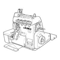
Juki MO-6000S series Engineer's Manual (94 pages)
Super-High-Speed Overlock Machine; High-Speed Overlock Machine / Safety Stitch Machine; High-Speed Variable Top Feed Overlock Machine
Brand: Juki
|
Category: Sewing Machine
|
Size: 1.05 MB
Table of Contents
Advertisement
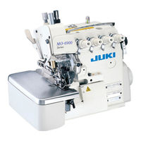
JUKI MO-6000S series Engineer's Manual (96 pages)
Super-High-Speed Ovelock Machine, High-Speed Ovelock Machine/Safety Stitch Machine, for Extra-heavy-weight Materials, High-Speed Variable Top Feed Overlock Machine
Brand: JUKI
|
Category: Sewing Machine
|
Size: 4.02 MB
Table of Contents

JUKI MO-6000S series Engineer's Manual (96 pages)
SupermHlghcSpeed Overlock Machine High.Speed Overlock Machine/ Safety Stitch Machine / HighcSpeed Variable Top Feed Overlock Machine
Brand: JUKI
|
Category: Sewing Machine
|
Size: 27.65 MB
Table of Contents
Advertisement
Advertisement