Sign In
Upload
Manuals
Brands
JUKI Manuals
Sewing Machine
LK-1902BN
JUKI LK-1902BN Manuals
Manuals and User Guides for JUKI LK-1902BN. We have
1
JUKI LK-1902BN manual available for free PDF download: Engineer's Manual
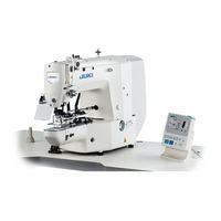
JUKI LK-1902BN Engineer's Manual (174 pages)
Computer-controlled High-speed Bartacking Machine
Brand:
JUKI
| Category:
Sewing Machine
| Size: 12.98 MB
Table of Contents
Table of Contents
13
1 Specifications
15
2 Configuration
19
N Ames Of Main Unit
19
N Ames And Explanation Of Switches On The Operation Panel
20
3 Standard Adjustment Value
22
Main Shaft Connection/Disconnection
22
Removal of the Main Shaft Motor and Coupling
24
Crank Connecting Rod Connection/Disconnection
26
Crank Balancer Positioning
28
Lower Shaft Backlash Adjustment and Connection/Disconnection
28
Adjustment of Hook Oil Amount
30
Oscillator Gear Positioning
30
Adjustment the Height of the Needle Bar
32
Shuttle Connection/Disconnection and Oil Wick Piping
32
10) H Ook Adjustment
34
11) T Hread Trimmer Cam Position Adjustment And Connection/Disconnection
36
12) T Hread Trimmer/Work Clamp Foot Origin Sensor Adjustment
36
13) a Djustment Of The Height Of The Work Clamp Foot
38
14) a Djustment Of The Thread Trimmer Sensor
38
15) a Djustment Of The Moving Knife And Counter Knife Position
40
16) a Djustment Of The Height Of The Moving Knife And Counter Knife
40
17) I Nclination Of The Blade Point Of The Counter Knife
42
18) F Loating Amount Of The Thread Tension Disk
42
19) S Econd Thread Tension Connection/Disconnection
44
20) a T Unit Connection/Disconnection
46
21) P Osition Of The Mechanical Origin
48
22) a Djustment Of The Y Origin
48
23) a Djustment Of The X Origin
50
24) a Djustment Of The Wiper Position
50
( 25) a Djustment Of The Wiper Spring (LK-1903B, 1903BN)
52
(Adjustment Of The Backlash Of The Driving Gear)
52
27) I Nstalling The Feed Plate Support Plate
54
28) I Nstallation Of The Feeder Bar Rear Cover
54
29) a Djustment Of The Bobbin Winder Driving Wheel Position
56
30) a Djustment Of The Bobbin Winder Amount
56
( 31) a Djustment of the Shuttle Upper Spring Position ( Except for LK-1900B-BS, 1900B-BF, 1903B-BS, 1900BN-BS, 1900BN-BF and 1903BN-BS)
58
32) S Huttle Felt
58
33) S Hape Of The Inner Hook Presser
60
34) a Djustment Of The Thread Take-Up Spring
60
35) N Eedle Thread Clamp Device Connection/Disconnection
62
36) a Djustment Of The Needle Thread Clamp Reference Position
64
37) a Djustment Of The Needle Thread Clamp Notch
66
39) a Ssembling The Moving Knife Drive Section Of Shorter Thread Remaining
68
Assembling The Shorter Thread Remaining Unit
68
40) a Ssembling The Suction Pipe
70
( 41) a Djustment of the Shuttle Upper Spring Position (LK-1903B-BS, 1900B-BS, 1900B-BF, 1903BN-BS, 1900BN-BS, 1900BN-BF) and the Lower Thread Holder Position (LK-1903BN-BS)
72
42) B Obbin Case With An Idling Prevention Spring
74
500 D Escription Of The Functions
75
To Use the Functions of the Serviceperson Level
75
Contrast Adjustment
76
USB Format
76
K Ey Lock Setting
77
H Ow To Check The Version Infoemation
79
How to Use the Communication Function (Communication Functions Other than NFC)
80
Registering an NFC Terminal
84
Pattern Selection from the USB Thumb Drive
87
5 Memory Switches
88
Memory Switch Start and Change
88
Table of Memory Switch Functions
89
Supplement for the Memory Switch
96
6 Check Program
98
Starting the Check Program
98
Input Signal Check
99
X/Y Motor Origin Adjustment
100
Continuous Operation
101
Main Motor Rpm Check
102
Output Check
102
Work Clamp Foot/Thread Trimming Motor Origin Adjustment
103
Needle Thread Clamp Motor Origin Adjustment
104
7 Miscellaneous
105
Various Printed Wiring Boards
105
T Able Of Bar-Tacking Standard Pattern Specifications
110
Table of Standard Patterns
111
8 Sub-Class Information
113
M Odels Classified By Button Sizes (LK-1903B)
113
T Able Of Standard Patterns (LK-1903B)
114
Option (LK-1900BB, 1903BB, 1900BNB, 1903BNB)
114
9 Optional Features
115
Table of Optional Parts
115
Connection of the Optional Pedal
117
Connection of the Magnet Wiper (Cannot be Connected with LK-1901B)
121
Connection of the Pause Switch
121
Connection of the Marking Light
122
Connection of the Needle Cooler (Turns on While Machine Is Running)
123
Table of the Work Clamp Foot
124
10 Maintenance
126
Replacing the Fuse
126
Specification Changeover
126
Greasing Parts
127
Parts to Which Grease Is Applied
128
Grease-Up Procedures for the Specified Position
136
11 Error List
137
2. T Roubles And Corrective Measures
142
Mechanical Parts
142
Sewing Conditions
144
Electrical Components
153
B Lock Diagram_Standard Specification (MC-670)
161
Block Diagram_Lk-1900BB, 1903BB (MC-672)
162
Block Diagram_Nfc Type (MC-672)
163
Power Supply Circuit Diagram (Single-Phase)
164
13 Circuit Diagrams
161
P Ower Supply Circuit Diagram (Single-Phase Ce)
165
P Ower Supply Circuit Diagram (3-Phase)
166
S Ervo Motor Circuit Diagram
167
Stepping Motor Circuit Diagram
168
MAIN · Operation Panel Circuit Diagram
169
Machine Head Sensor Circuit Diagram
170
( 11) a Ir Circuit Diagram (LK-1900Bb And 1903Bb Only)
171
12) P Neumatic Circuit Diagram For Lk-1900BB
171
T Able Type For Longitudinal Installation
172
14 Table Drawings
172
T Able Type For Lateral Installation
173
Advertisement
Advertisement
Related Products
JUKI LK-1902A-SS
JUKI LK-1902A-HS
JUKI LK-1902AN-SS
JUKI LK-1902AN-HS
Juki LK-1902A
JUKI LK-1902
JUKI LK-1902S
JUKI LK-1902H
JUKI LK-1902B
JUKI LK-1902AN
JUKI Categories
Sewing Machine
Industrial Equipment
Sewing Machine Accessories
Accessories
Trimmer
More JUKI Manuals
Login
Sign In
OR
Sign in with Facebook
Sign in with Google
Upload manual
Upload from disk
Upload from URL