Sign In
Upload
Manuals
Brands
Johnson Controls Manuals
Chiller
York YCRL0198SE
Johnson Controls York YCRL0198SE Manuals
Manuals and User Guides for Johnson Controls York YCRL0198SE. We have
1
Johnson Controls York YCRL0198SE manual available for free PDF download: Installation Operation & Maintenance
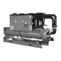
Johnson Controls York YCRL0198SE Installation Operation & Maintenance (162 pages)
WATER-COOLED LIQUID CHILLERS HERMETIC SCROLL
Brand:
Johnson Controls
| Category:
Chiller
| Size: 7.22 MB
Table of Contents
Table of Contents
6
FIGURE 1 - YCRL Water Cooled Liquid Chiller
17
Chiller Options
21
Final Paint Overspray
21
Service Isolation Valve
21
Hot Gas By-Pass
21
Compressor Acoustic Sound Blanket
21
Vibration Isolation
21
Neoprene Isolation
21
One Inch Spring Isolators
21
Two Inch Seismic Isolators
21
Control / Power Panel Components
22
FIGURE 2 - Control/Panel Components
22
FIGURE 3 - Control Power Panel Components
23
FIGURE 4 - Unit Components
24
FIGURE 5 - Refrigerant Flow Diagram (Standard)
29
Refrigerant Flow Diagram - YCRL (European)
30
Product Identification Number (Pin)
25
Refrigerant Flow Diagram - YCRL (Standard)
29
Unit Components
24
FIGURE 6 - Refrigerant Flow Diagram (European)
30
Section 3 - Transportation, Handling and Storage
31
Delivery and Storage
31
Inspection
31
Moving the Unit
31
Lifting by Crane / Hoist
31
Lifting Weights
32
FIGURE 7 - Chiller Rigging and Lifting Weights
32
Section 4 - Installation
33
Foundation
33
Installation Checklist
33
Location Requirements
33
Unit Isolation (Noise Sensitive Location)
33
Chilled Liquid Pipework Connection
34
General Requirements
34
Installation of Vibration Isolators
34
Condenser Relief Valve
36
FIGURE 8 - Victaulic - Adapter Flanges
36
Option Flanges
36
Refrigerant Relief Valve Piping
36
Water Treatment
36
Glycol Solutions
36
Connection Types and Sizes
37
Cooler Connections
37
FIGURE 11 - Cooler Connections
37
FIGURE 12 - Example of Typical Effect of Suction and Discharge Line Pressure Drop
38
TABLE 2 - Discharge and Liquid Line Capacities in Tons for Refrigerant 410A
40
Control Panel Wiring
43
Flow Switch (SF)
43
Remote Start/Stop
43
TABLE 3 - Minimum Refrigeration Capacity in Tons for Oil Entrain up Hot Gas Risers (Type L Copper Tubing) . 41
43
FIGURE 10 - Pipework Arrangements Legend
37
FIGURE 9 - Chilled Liquid System
37
Electrical Connection
42
Chilled Liquid Pump (CLP) (Evaporator Pump Start Contacts)
42
Remote Emergency Stop Device
42
System Alarm (SA) (System Alarm Contacts)
42
System Run Contacts
42
Field Wiring
42
YCRL Connection Sizes
42
YCRL Chiller Charge Capability
43
TABLE 4 - YCRL Connection Line Sizes
43
TABLE 5 - YCRL Chiller Charges
43
Compressor Heaters
44
High Pressure Cutout
44
Power Wiring
44
Control Transformer Primary Voltage Tappings
44
Units with Multi Point Power Supply Wiring
44
Units with Single-Point Power Supply Wiring
44
Relief Valves
44
Control Wiring
45
Pipework Arrangement
37
TABLE 1 - Condenser / Cooler Connections
37
Pressure Drop Considerations
38
Refrigerant Line Losses
38
Refrigerant Line Sizing
38
Remote Condenser Piping
38
Chiller below Condenser
39
Condenser below Chiller
39
Oil Traps
39
Refrigerant Charge
39
Refrigerant Piping Reference
39
R-410A Copper Line Sizing
39
YCRL Line Sizing Notes
39
FIGURE 13 - Control Wiring
45
TABLE 6 - Temperatures and Flows
47
TABLE 7 - Voltage Limitations
47
Section 5 - Technical Data
47
Operational Limitations (English and SI)
47
Voltage Limitations
47
FIGURE 14 - Evaporator Water Pressure Drop Curves (English and SI)
48
Pressure Drop Charts
48
Ethylene and Propolyne Glycol Correction Factors
49
Evaporator Pressure Drop
49
FIGURE 15 - Glycol Solution Strengths
49
FIGURE 16 - Single Point Power Supply Connection - Standard Unit
56
FIGURE 17 - Dual Point Power Supply Connection - Optional
57
Electrical Data
58
TABLE 10 - Micro Panel Power Supply
58
TABLE 11 - Voltage Range (Limitations)
58
Electrical Notes
59
TABLE 12 - Ground Lug Sizing
60
Elementary Wiring Diagram
62
FIGURE 18 - Standard Power, Single Point and Multiple Point Control Panel Wiring
62
Wiring Diagrams
62
TABLE 8 - Ethylene and Propolyne Glycol Correction Factors
49
TABLE 9 - Recommended Glycol Solution Strengths
49
Single-Point Supply Connection - Terminal Block, Non-Fused Disconnect Switch or Circuit Breaker
56
Dual-Point Supply Connection - Terminal Block, Non-Fused Disconnect Switch or Circuit Breaker
57
Physical Data - Standard and High Efficiency - English
50
Electrical Data - Single Point
52
Electrical Data - Dual Point
54
FIGURE 19 - Standard Power, Single Point and Multiple Point Control Panel Wiring, 6 Compressor Unit
64
FIGURE 20 - Standard Power and Single Point Power Circuit, 4 Compressor Unit
66
FIGURE 21 - Multiple Point Power Circuit, 4 Compressor Unit
67
FIGURE 22 - Standard Power and Single Point Power Circuit, 6 Compressor Unit
68
FIGURE 23 - Multiple Point Power Circuit, 6 Compressor Unit
69
FIGURE 24 - Standard Power and Single Point Connection Wiring Diagram, 4 Compressor Unit
70
FIGURE 25 - Multiple Point Power Connection Wiring Diagram, 4 Compressor Unit
72
FIGURE 26 - Standard Power and Single Point Connection Wiring Diagram, 6 Compressor Unit
74
FIGURE 27 - Multiple Point Connection Wiring Diagram, 6 Compressor Unit
76
FIGURE 28 - Standard Power, Single Point and Multiple Point Elementary Wiring Diagram Details
78
FIGURE 29 - Standard Power, Single Point and Multiple Point Elementary Wiring Diagram Details
80
FIGURE 30 - EEV Controller Wiring
82
Unit Dimensions - English - Four Compressor
83
Unit Dimensions - English - Six Compressor
84
Isolator Selection Data
85
Isolator Information
86
One Inch Deflection Spring Isolators Installation Instructions
87
Installation of Duralene Vibration Isolators
89
Seismic Isolator Installation and Adjustment
91
Section 6 - Commissioning
93
General
93
Preparation - Power off
93
Inspection
93
Refrigerant Charge
93
Service and Oil Line Valves
93
Compressor Oil
93
Isolation / Protection
93
Control Panel
93
Power Connections
93
Grounding
94
Supply Voltage
94
Preparation - Power on
94
Switch Settings
94
Compressor Heaters
94
Water System
94
Flow Switch
94
Temperature Sensor(S)
94
Equipment Pre Start-Up and Start-Up Checklist
95
Pre Start-Up
95
Checking the System Prior to Initial Start (no Power)
95
Compressor Heaters (Power on - 24 Hours Prior to Start)
95
Unit Checks
95
Start-Up
95
Panel Checks (Power on - Unit Switch Off)
95
TABLE 13 - Setpoints Entry List
96
Checking Superheat and Subcooling
97
Leak Checking
97
Unit Operating Sequence
98
Section 7 - Unit Controls
99
Introduction
99
IPU II and I/O Boards
99
Unit Switch
100
Display
100
Keypad
100
Battery Back-Up
100
Transformer
100
Programming # of Compressors
100
Status Key
101
General Status Messages
101
Unit Status
101
Fault Safety Status Messages
103
System Safeties
103
Unit Safeties
104
Unit Warning
105
FIGURE 31 - Status Key Messages Quick Reference List
106
Status Key Messages
106
FIGURE 32 - Operation Data
110
TABLE 14 - Cooling Setpoints, Programmable Limits and Defaults
118
Program Key
119
System Trip Volts
120
Unit Trip Volts
121
Entry Keys
115
Enter/Adv Key
115
Up and down Arrow Keys
115
Setpoints Keys
116
Cooling Setpoints
116
Leaving Chilled Liquid Control
116
Remote Setpoint Control
117
Return Chilled Liquid Control
117
Schedule/Advance Day Key
117
Display/Print Keys
107
Oper Data Key
107
Oper Data Quick Reference List
110
Print Key
111
Operating Data Printout
111
History Printout
112
History Displays
112
Software Version
114
TABLE 15 - Program Key Limits and Default
121
FIGURE 33 - Setpoints Quick Reference List
122
FIGURE 34 - Unit Keys Options Programming Quick Reference List
128
Capacity Control
129
Discharge Pressure Limit Controls
129
Unit Keys
123
Options Key
123
Option 1 - Language
123
Option 2 - System Switches
123
Option 3 - Chilled Liquid Cooling Type
123
Option 4 - Ambient Control Type
124
Option 5 - Local/Remote Control Type
124
Option 6 - Unit Control Mode
124
Option 7 - Display Units
124
Option 8 - Lead/Lag Type (Two System Units Only)
124
Option 9 - Condenser Fan Control Mode
124
Option 10 - Manual Override Mode
125
Option 11 - Current Feedback Options Installed
125
Option 12 - Power Fail Restart
125
Option 13 - Soft Start Enable/Disable
125
Option 14 - Unit Type
125
Option 15 - Refrigerant Type
126
Option 16 - Expansion Valve Type
126
Option 17 - Flash Card Update
126
Option 18 - Remote Temperature Reset
126
Option 19 - Pump Control
127
Option 20 - Pump Selection
127
Clock
127
Section 8 - Unit Operation
129
FIGURE 35 - Leaving Water Temperature Control Example
129
FIGURE 36 - Setpoint Adjust
130
Leaving Chilled Liquid Control Override to Reduce Cycling
130
Leaving Chilled Liquid System Lead/Lag and Compressor Sequencing
130
Return Chilled Liquid Control
131
Leaving Chilled Liquid Control
129
Suction Pressure Limit Controls
129
TABLE 17 - Return Chilled Liquid Control for 4 Compressors (6 Steps)
131
TABLE 18 - Return Chilled Liquid Control for 4 Compressors (6 Steps)
132
TABLE 19 - Compressor Operation - Load Limiting
133
Alarm Status
134
Bas/Ems Temperature Reset Usinga Voltage or Current Signal
134
EMS-PWM Remote Temperature Reset
134
VDC Pressure Setting Guidelines
135
Anti-Coincidence Timer
133
Compressor Run Status
133
Evaporator Heater Control
133
Evaporator Pump Control and York Hydro Kit Pump Control
133
Load Limiting
133
Pumpdown Control
133
TABLE 16 - Sample Compressor Staging for Return Water Control
131
Anti-Recycle Timer
132
Return Chilled Liquid System Lead/Lag and Compressor Sequencing
132
Section 9 - Service and Troubleshooting
137
Clearing History Buffers
137
Service Mode
137
Service Mode - Outputs
137
Service Mode - Analog and Digital Inputs
138
Service Mode - Chiller Configuration
138
Control Inputs/Outputs
139
TABLE 22 - I/O Analog Inputs
139
FIGURE 37 - Microboard Layout
140
TABLE 24 - Entering/Leaving Chilled Liquid Temperature Sensor, Temperature/Voltage Correlation
141
Analog Inputs - Pressure
142
TABLE 25 - Pressure Transducers
142
Digital Outputs
143
FIGURE 38 - I/O Board Relay Contact Architecture
143
Assembly and Wiring
144
Obtaining a Printout
144
Optional Printer Installation
144
Parts
144
TABLE 23 - I/O Analog Outputs
139
Checking Inputs and Outputs
141
Analog Inputs - Temperature
141
Digital Inputs
141
Liquid and Refrigerant Sensor Test Points
141
FIGURE 39 - Printer to Microboard Electrical Connections
144
TABLE 26 - Troubleshooting
145
Troubleshooting
145
TABLE 21 - I/O Digital Outputs
139
TABLE 20 - I/O Digital Inputs
139
Microboard Layout
140
Section 10 - Maintenance
147
Compressors
147
Oil Level Check
147
Oil Analysis
147
Important
147
On-Board Battery Back-Up
147
Operating Parameters
147
Overall Unit Inspection
147
Bacnet, Modbus and Yorktalk 2 Communications
148
TABLE 27 - Minimum, Maximum and Default Values
149
FIGURE 40 - Micro Panel Connections
149
TABLE 28 - Values Required for Bas Communication
150
TABLE 29 - Real Time Error Numbers
150
TABLE 30 - Bacnet and Modbus Communications Data Map
152
TABLE 31 - Yorktalk 2 Communications Data Map
156
Temperature Conversion Chart
159
R410-A Pressure Temperature Chart
160
TABLE 32 - si Metric Conversion
161
Temperature
161
Yorktalk 2 Communications
155
Received Data (Control Data)
155
Transmitted Data
155
Bacnet and Modbus Communications
151
Analog Write Points
151
Binary Write Points
151
Analog Read Only Points
151
Binary Monitor Only Points
151
Communications Data Map Notes
151
Advertisement
Advertisement
Related Products
Johnson Controls York YCRL0118
Johnson Controls York YCRL0126
Johnson Controls York YCRL0156
Johnson Controls York YCRL0177
Johnson Controls York YCRL0198
Johnson Controls York YCRL0118HE
Johnson Controls York YCRL0126HE
Johnson Controls York YCRL0156HE
Johnson Controls York YCRL0177SE
Johnson Controls York YCRL0064HE
Johnson Controls Categories
Controller
Air Conditioner
Thermostat
Control Unit
Irrigation System
More Johnson Controls Manuals
Login
Sign In
OR
Sign in with Facebook
Sign in with Google
Upload manual
Upload from disk
Upload from URL