Sign In
Upload
Manuals
Brands
Intel Manuals
Computer Hardware
VC820 - Desktop Board Motherboard
Intel VC820 - Desktop Board Motherboard Manuals
Manuals and User Guides for Intel VC820 - Desktop Board Motherboard. We have
1
Intel VC820 - Desktop Board Motherboard manual available for free PDF download: Design Manual
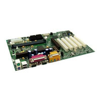
Intel VC820 - Desktop Board Motherboard Design Manual (242 pages)
Chipset
Brand:
Intel
| Category:
Computer Hardware
| Size: 4.13 MB
Table of Contents
Table of Contents
3
Revision History
9
Introduction
11
About this Design Guide
13
References
14
System Overview
14
Chipset Components
15
Bandwidth Summary
16
System Configuration
17
820 Chipset Platform Dual-Processor Performance Desktop Block Diagram
19
Platform Initiatives
20
Direct Rambus
20
Streaming SIMD Extensions
20
Agp 2.0
20
Hub Interface
20
Manageability
21
AC'97 Connections
23
Low Pin Count (LPC) Interface
23
Layout/Routing Guidelines
27
General Recommendations
27
Component Quadrant Layout
27
MCH 324-Ubga Quadrant Layout (Top View)
28
ICH 241-Ubga Quadrant Layout (Top View)
28
Sample ATX MCH/ICH Component Placement
29
Intel ® 820 Chipset Component Placement
29
Primary Side MCH Core Routing Example (ATX)
30
Core Chipset Routing Recommendations
30
Secondary Side MCH Core Routing Example (ATX)
31
Source Synchronous Strobing
31
AGP 2X Data/Strobe Association
32
Data Strobing Example
32
Effect of Crosstalk on Strobe Signal
32
RIMM Diagram
33
Stackup
34
Direct Rambus* Layout Guidelines
34
Direct Rambus* Interface
33
Placement Guidelines for Motherboard Routing Lengths
35
RSL Routing Dimensions
35
RSL Routing Diagram
35
Primary Side RSL Breakout Example
36
Secondary Side RSL Breakout Example
37
Direct RDRAM Termination
37
Direct Rambus* Termination Example
38
Incorrect Direct Rambus* Ground Plane Referencing
39
Direct Rambus Ground Plane Reference
39
Copper Tab Area Calculation
41
Connector Compensation Example
42
Bottom Layer
46
Rsl Signal Layer Alternation
46
RSL Routing Layer Requirements
47
RSL Signal Layer Alternation
47
RDRAM Trace Length Matching Example
48
Dummy" Via Vs. Real "Via
49
Line Matching and Via Compensation Example
50
Direct Rambus* Reference Voltage
51
High-Speed CMOS Routing
51
Ramref Generation Example Circuit
51
High-Speed CMOS Termination
52
SIO Routing Example
52
RDRAM CMOS Shunt Transistor
53
Direct Rambus* Clock Routing
54
Direct Rambus* Design Checklist
54
Signal List
54
Agp 2.0
57
AGP Interface Signal Groups
58
Timing Domain Routing Guidelines
59
4X Timing Domain Routing Guidelines
59
AGP 2.0 Data/Strobe Associations
59
AGP 2X/4X Routing Example for Interfaces < 6"
60
AGP 2.0 Routing Summary
61
AGP Clock Routing
62
General AGP Routing Guidelines
62
VDDQ Generation and TYPEDET
63
Top Signal Layer
63
TYPDET#/VDDQ Relationship
64
VREF Generation for AGP 2.0 (2X and 4X)
65
AGP VDDQ Generation Example Circuit
65
AGP 2.0 VREF Generation & Distribution
66
Compensation
67
AGP Pull-Ups
67
Motherboard / Add-In Card Interoperability
68
Connector/Add-In Card Interoperability
68
Voltage/Data Rate Interoperability
68
Hub Interface Signal Routing Example
69
Data Signals
70
Strobe Signals
70
HREF Generation/Distribution
70
Hub Interface
69
Single Hub Interface Reference Divider Circuit
70
Locally Generated Hub Interface Reference Dividers
71
System Bus Design
72
100/133 Mhz System Bus
72
Segment Descriptions and Lengths for Figure
72
System Bus Ground Plane Reference
73
Grounding Retention Mechanism (GRM)
73
Ground Plane Reference (Four Layer Motherboard)
73
Hole Locations and Keepout Zones for Support Components
74
Grounding Pad Dimensions for the SECC2 GRM
74
Processor CMOS Pullup Values
75
Processor and 82820 MCH Connection Checklist
75
Additional Host Bus Guidelines
78
Bus Request Connection Scheme for DP Intel
78
820 Chipset Designs
78
TCK/TMS Implementation Example for DP Designs
78
Single Processor BREQ Strapping Requirements
78
BREQ0# Circuitry for DP Systems
79
Dual-Processor BREQ Strapping Requirements
79
HA7# Strapping Option Example Circuit (for Debug Purposes Only)
80
Ultra ATA/66
82
Ultra ATA/66 Detection
82
Ultra ATA/66 Cable Detection
83
Host-Side IDE Cable Detection
83
Drive-Side IDE Cable Detection
84
Layout for Host- or Drive-Side IDE Cable Detection
85
Ultra ATA/66 Cable
85
Ultra ATA/66 Pullup/Pulldown Requirements
86
Resistor Requirements for Primary IDE Connector
86
Ac'97
87
Resistor Requirements for Secondary IDE Connector
87
ICH Codec Options
87
Tee Topology AC'97 Trace Length Requirements
88
Daisy-Chain Topology AC'97 Trace Length Requirements
88
AC'97 Signal Quality Requirements
89
AC'97 Motherboard Implementation
89
AC'97 SDIN Pulldown Resistors
89
USB Data Signals
91
Usb
91
Isa (82380Ab)
92
ICH GPIO Connected to 82380AB
92
Sub Class Code
92
IOAPIC Design Recommendation
92
PCI Bus Layout Example
93
RTC Crystal
94
External Capacitors
94
Smbus/Alert Bus
93
Pci
93
Rtc
93
External Circuitry for the ich RTC
94
RTC Layout Considerations
95
RTC External Battery Connection
95
Diode Circuit Connecting RTC External Battery
95
RTC External RTCRST Circuit
96
RTC Routing Guidelines
96
RTCRST External Circuit for the ich RTC
96
VBIAS DC Voltage and Noise Measurements
97
Advanced System Bus Design
99
Terminology and Definitions
101
AGTL+ Design Guidelines
104
Initial Timing Analysis
105
AGTL+ Parameters for Example Calculations
106
Example TFLT_MAX Calculations for 133 Mhz Bus
107
Determine General Topology, Layout, and Routing Desired
108
Pre-Layout Simulation
108
Example TFLT_MIN
108
Place and Route Board
110
Trace Width Space Guidelines
111
PICD[1,0] Uni-Processor Topology
112
PICD[1,0] Dual-Processor Topology
112
Host Clock Routing
112
Post-Layout Simulation
113
Validation
114
Test Load Vs. Actual System Load
114
Theory
115
Agtl
115
Timing Requirements
116
Cross-Talk Theory
116
Aggressor and Victim Networks
117
Transmission Line Geometry: (A) Microstrip (B) Stripline
117
More Details and Insight
119
Textbook Timing Equations
119
Effective Impedance and Tolerance/Variation
120
Power/Reference Planes, PCB Stackup, and High Frequency Decoupling
120
One Signal Layer and One Reference Plane
121
Layer Switch with One Reference Plane
121
Layer Switch with Multiple Reference Planes (same Type)
121
Layer Switch with Multiple Reference Planes
122
One Layer with Multiple Reference Planes
122
Clock Routing
123
Definitions of Flight Time Measurements/Corrections and Signal Quality
124
Ringback Levels
124
VREF Guardband
124
Overdrive Region
124
REF Guardband
124
Flight Time Definition and Measurement
125
Overdrive Region and
125
Rising Edge Flight Time Measurement
125
Conclusion
126
Clocking
127
Intel ® 820 Chipset Platform System Clocks
129
Clock Generation
129
Intel ® 820 Chipset Platform Clock Distribution
130
Intel ® 820 Chipset Platform Clock Skews
131
Intel ® 820 Chipset Clock Routing Guidelines
132
Intel ® 820 Chipset Platform System Clock Cross-Reference
133
Component Placement and Interconnection Layout Requirements
134
14.318 Mhz Crystal to CK133
134
CK133 to DRCG
134
CK133 to DRCG Routing Diagram
134
MCH to DRCG
135
MCH to DRCG Routing Diagram
135
Direct Rambus* Clock Routing Dimensions
135
DRCG to RDRAM Channel
136
Trace Length
136
Placement Guidelines for Motherboard Routing Lengths
136
Trace Geometry
136
Differential Clock Routing Diagram (Section 'A', 'C', & 'D')
137
Non-Differential Clock Routing Diagram (Section 'B')
137
Termination for Direct Rambus* Clocking Signals CFM/CFM
137
DRCG Impedance Matching Circuit
138
External DRCG Component Values
138
DRCG Layout Example
139
DRCG Impedance Matching Network
138
AGP Clock Routing Guidelines
139
Series Termination Resistors for CK133 Clock Outputs
139
Bottom Layer
139
Unused Outputs
140
Decoupling Recommendation for CK133 and DRCG
140
DRCG Frequency Selection and the DRCG
140
DRCG Frequency Selection Table and Jitter Specification
140
Unused Output Termination
140
DRCG Ratio
140
DRCG+ Frequency Selection Schematic
141
DRCG+ Frequency Selection
141
System Manufacturing
143
In Circuit LPC Flash BIOS Programming
145
Stackup Requirement
145
Overview
145
PCB Materials
146
Design Process
146
Ω Trace Geometry
146
Test Coupon Design Guidelines
147
Recommended Stackup
147
Inner Layer Routing
147
Ω Stackup Examples
147
Impedance Calculation Tools
148
Testing Board Impedance
148
Microstrip and Stripline Cross-Section for 28 Ω Trace
148
D Field Solver Vs ZCALC
148
Board Impedance/Stackup Summary
149
Mil Stackup (Not Routable)
149
Mil Stackup
149
System Design Considerations
151
Power Delivery
153
Terminology and Definitions
153
V and 2.5V Power Sequencing (Schottky Diode)
156
64/72Mbit RDRAM Excessive Power Consumption
157
Use a GPO to Reduce DRCG Frequency
158
Power Plane Splits
159
Thermal Design Power
159
Power Plane Split Example
159
Glue Chip 3 Vendors
160
Reference Design Schematics: Uni-Processor
163
Reference Design Feature Set
163
Usb Connectors
186
Power Connector
194
Reference Design Schematics: Dual-Processor
203
Reference Design Feature Set
203
Advertisement
Advertisement
Related Products
Intel VROC
Intel VIA K8T800
Intel Mobileye Shield+ v2.0
Intel VCA1283LVV
Intel VCA 2
Intel VCA1585LMV
Intel VCA
Intel Vision HT Series
Intel Vectra VEi7
Intel vPro
Intel Categories
Motherboard
Computer Hardware
Server
Server Board
Desktop
More Intel Manuals
Login
Sign In
OR
Sign in with Facebook
Sign in with Google
Upload manual
Upload from disk
Upload from URL