Sign In
Upload
Manuals
Brands
Intel Manuals
Desktop
SR1530 - AHJPCIERISER PCI-E x8 Riser Card
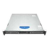
Intel SR1530 - AHJPCIERISER PCI-E x8 Riser Card Manuals
Manuals and User Guides for Intel SR1530 - AHJPCIERISER PCI-E x8 Riser Card. We have
2
Intel SR1530 - AHJPCIERISER PCI-E x8 Riser Card manuals available for free PDF download: User Manual, Technical Product Specification
Intel SR1530 - AHJPCIERISER PCI-E x8 Riser Card User Manual (184 pages)
User Guide
Brand:
Intel
| Category:
Desktop
| Size: 6.42 MB
Table of Contents
Safety Information
3
Important Safety Instructions
3
Wichtige Sicherheitshinweise
3
Consignes de Sécurité
3
Instrucciones de Seguridad Importantes
3
Warnings
5
Preface
7
About this Manual
7
Manual Organization
7
Product Contents
8
Intel ® Server System SR1530AH / SR1530AHLX Contents
8
Intel ® Server System SR1530HAHLX Contents
9
Server System References
10
Table of Contents
11
List of Figures
19
Chapter 1: Server System Features
23
Figure 1. Intel ® Server System SR1530AH/SR1530AHLX
23
Figure 2. Intel ® Server System SR1530HAHLX
23
Table 2. Intel ® Server System SR1530AH / SR1530AHLX / SR1530HAHLX Feature Summary
26
Chassis Component Identification
27
System Front Panel (SR1530AH / SR1530AHLX)
27
Figure 3. Front Controls and Leds (SR1530AH / SR1530AHLX)
27
System Front Panel (SR1530HAHLX)
28
Figure 4. Front Controls and Leds (SR1530HAHLX)
28
System Rear
29
Table 3. NIC LED Descriptions
29
Figure 5. Back Panel Connectors
29
Peripheral Devices (SR1530AH / SR1530AHLX)
30
Figure 6. Optional Peripherals (SR1530AH / SR1530AHLX)
30
Peripheral Devices (SR1530HAHLX)
31
Figure 7. Optional Peripherals (SR1530HAHLX)
31
Slimline Optical Drive Carrier
32
Internal Components (SR1530AH / SR1530AHLX)
33
Figure 8. System Components (SR1530AH / SR1530AHLX)
33
Internal Components (SR1530HAHLX)
34
Figure 9. System Components (SR1530HAHLX)
34
Figure 10. S3000AHLX Connector and Component Locations
35
Server Board Connectors / Components
35
Figure 11. S3000AH Connector and Component Locations
36
Configuration Jumpers
37
Figure 12. Configuration Jumper Descriptions
37
Hardware Requirements
38
Processor
38
Memory
39
RAID Support
38
Chapter 2: Server Utilities
41
Using the BIOS Setup Utility
41
Starting Setup
41
If You Cannot Access Setup
41
Setup Menus
41
Table 4. Setup Menu Key Use
42
Upgrading the BIOS
43
Preparing for the Upgrade
43
Upgrading the BIOS
44
Clearing the CMOS
45
Figure 13. Clear CMOS Jumper
45
Chapter 3: Hardware Installations and Upgrades
47
Before You Begin
47
Tools and Supplies Needed
47
System References
47
Removing and Installing the Front Bezel
48
Removing the Front Bezel
48
Figure 14. Removing the Front Bezel
48
Installing the Front Bezel
49
Figure 15. Installing the Front Bezel
49
Removing and Installing the Server Cover
50
Removing the Server System Cover
50
Figure 16. Removing the Server System Cover (SR1530AH/SR1530AHLX)
50
Figure 17. Removing the Server System Cover (SR1530HAHLX)
51
Installing the Server System Cover
52
Figure 18. Installing the Server System Cover (SR1530AH/SR1530AHLX)
52
Removing and Installing the Processor Air Duct
53
Removing the Processor Air Duct
53
Figure 19. Installing the Server System Cover (SR1530HAHLX)
53
Figure 20. Removing the Processor Air Duct (SR1530AH/SR1530AHLX)
54
Figure 21. Removing the Processor Air Duct (SR1530HAHLX)
54
Installing the Processor Air Duct
55
Figure 22. Installing the Processor Air Duct (SR1530AH/SR1530AHLX)
55
Installing and Removing Memory
56
Installing Dimms
56
Figure 23. Installing the Processor Air Duct (SR1530HAHLX)
56
Figure 24. Installing the Memory
57
Removing Dimms
58
Replacing the Processor
59
Removing the Heat Sink and Processor
59
Installing the Processor
60
Figure 25. Lifting the Processor Socket Handle
60
Figure 26. Opening the Load Plate
60
Figure 27. Removing the Shipping Cover
61
Figure 28. Installing the Processor
61
Figure 29. Removing the Protective Socket Cover
61
Installing the Heat Sink
62
Figure 30. Installing the Heat Sink
62
Installing and Removing a Hard Drive (SR1530AH / SR1530AHLX)
63
Installing a Hard Disk Drive (SR1530AH/SR1530AHLX)
63
Figure 31. Locating Drive Positions (SR1530AH/SR1530AHLX)
64
Figure 32. Removing Drive Carrier from the Server System (SR1530AH/SR1530AHLX)
64
Figure 33. Installing Drive into Drive Carrier (SR1530AH/SR1530AHLX)
65
Figure 34. Install Drive Assembly into the Server System (SR1530AH/SR1530AHLX)
65
Figure 35. Connecting Hard Drive Power and Data Cables (SR1530AH/SR1530AHLX)
66
Removing a Hard Disk Drive (SR1530AH/SR1530AHLX)
67
Figure 36. Removing Drive Carrier from the Server System (SR1530AH/SR1530AHLX)
67
Figure 37. Install Drive Carrier into the Server System (SR1530AH/SR1530AHLX)
68
Installing and Removing a Hot-Swap SATA Drive (SR1530HAHLX)
69
Installing a Hot-Swap SATA Drive (SR1530HAHLX)
69
Figure 38. Locating Drive Positions (SR1530HAHLX)
69
Figure 39. Removing the Drive Carrier (SR1530HAHLX)
70
Figure 40. Installing Drive into Drive Carrier (SR1530HAHLX)
70
Removing a Hot-Swap SATA Drive (SR1530HAHLX)
71
Figure 41. Install Drive Assemby into the Server System (SR1530HAHLX)
71
Installing or Removing a Slimline Optical Drive (SR1530AH / SR1530AHLX)
72
Installing a Slimline Optical Drive
72
Figure 42. Lifting PCI Cooling Fan from Mounting Pegs (SR1530AH/SR1530AHLX)
73
Figure 43. Removing the Knock-Out from the Sheet Metal Panel
73
Figure 44. Attaching the Interposer Board
74
Figure 45. Attaching the Optical Drive to the Brackets
74
Figure 46. Installing the Optical Drive into the System
75
Figure 47. Installing the PCI Cooling Fan (SR1530AH/SR1530AHLX)
75
Removing a Slimline Optical Drive
76
Figure 48. Lifting PCI Cooling Fan from Mounting Pegs (SR1530AH/SR1530AHLX)
76
Figure 49. Removing the Optical Drive from the Server System
77
Figure 50. Attaching the Optical Drive Bracket to the Brackets
77
Figure 51. Removing the Interposer Board from the Optical Drive
78
Figure 52. Installing the PCI Cooling Fan (SR1530AH/SR1530AHLX)
78
Installing or Removing a Slimline Optical Drive (SR1530HAHLX)
79
Installing a Slimline Optical Drive (SR1530HAHLX)
79
Figure 53. Attaching the Optical Drive to the Attachment Bracket
79
Removing a Slimline Optical Drive (SR1530HAHLX)
80
Figure 54. Installing the Optical Drive into the System
80
Figure 55. Removing the Optical Drive from the System
81
Figure 56. Removing the Optical Drive from the Attachment Bracket
81
Installing and Removing the PCI Riser Assembly
82
Removing the PCI Riser Assembly
82
Figure 57. Removing PCI Riser Assembly from the Server System
82
Installing the PCI Riser Assembly
83
Figure 58. Installing PCI Riser Assembly into the Server System
83
Installing or Replacing a PCI Riser Card
84
Removing a PCI Riser Card
84
Figure 59. Removing Riser Card from Riser Assembly
84
Installing a PCI Riser Card
85
Figure 60. Installing Riser Card Onto Riser Assembly
85
Installing and Removing a PCI Add-In Card
86
Installing a PCI Add-In Card
86
Removing a PCI Add-In Card
87
Figure 61. Installing an Add-In Card
87
Figure 62. Removing a Full Height Add-In Card
88
Replacing the Server Board
89
Removing the Server Board
89
Figure 63. Removing the Server Board
90
Installing the Server Board
91
Figure 64. Installing the Server Board
91
Replacing the CMOS Battery
92
Figure 65. Replacing the CMOS Battery
93
Replacing the Power Supply (SR1530AH / SR1530AHLX)
94
Figure 66. Disconnecting Power Cables (SR1530AH / SR1530AHLX)
95
Figure 67. Removing Power Supply from the Server System (SR1530AH / SR1530AHLX)
96
Figure 68. Installing Power Supply Module into the Server System (SR1530AH / SR1530AHLX)
97
Figure 69. Connecting Power Cables (SR1530AH / SR1530AHLX)
98
Replacing the Power Supply (SR1530HAHLX)
99
Figure 70. Removing Power Supply from the Server System (SR1530HAHLX)
99
Observe the Safety and ESD Precautions at the Beginning of this Book. See Information" on Page
99
Power down the Server and Unplug All Peripheral Devices and the AC Power Cable
99
Figure 71. Installing Power Supply Module into the Server System (SR1530HAHLX)
100
Replacing the Front Panel Board (SR1530AH/SR1530AHLX)
101
Figure 72. Removing Front Panel Board from the Server System (SR1530AH/SR1530AHLX)
101
Remove the Server System Cover. for Instructions, See System Cover" on Page
101
Figure 73. Installing Front Panel Board into the Server System (SR1530AH/SR1530AHLX)
102
Replacing the Front Panel Board (SR1530HAHLX)
103
Figure 74. Removing Front Panel Board from the Server System (SR1530HAHLX)
103
Figure 75. Removing Light Pipes from the Front Panel Board (SR1530HAHLX)
104
Figure 76. Installing Front Panel Board into the Server System (SR1530HAHLX)
104
Figure 77. Installing Light Pipes on the Front Panel Board (SR1530HAHLX)
105
Replacing a Cooling Fan (SR1530AH / SR1530AHLX)
106
Replacing the System Blower Fans (SR1530AH / SR1530AHLX)
106
Remove the Processor Air Duct. for Instructions, See
106
Figure 78. Disconnecting System Blower Fans (SR1530AH / SR1530AHLX)
107
Figure 79. Removing Bracket and System Blower Fans from Server System (SR1530AH / SR1530AHLX)
108
Figure 80. Removing Fan from Fan Bracket (SR1530AH / SR1530AHLX)
109
Figure 81. Connecting System Blower Fans (SR1530AH / SR1530AHLX)
110
Duct" on Page
110
Replacing the PCI Cooling Fan (SR1530AH/SR1530AHLX)
111
Figure 82. Disconnecting the PCI Cooling Fan (SR1530AH/SR1530AHLX)
111
Safety
111
Removing the Server
111
Figure 83. Removing the PCI Cooling Fan (SR1530AH/SR1530AHLX)
112
Replacing a Cooling Fan (SR1530HAHLX)
113
Replacing the System Blower Fans (SR1530HAHLX)
113
Figure 84. Removing Fan from the Server System (SR1530HAHLX)
113
Removing the Processor Air
113
Figure 85. Installing Fan into the Server System (SR1530HAHLX)
114
Installing and Removing the Rack Handles
115
Installing the Rack Handles
115
Figure 86. Installing the Rack Handle
115
Removing the Rack Handles
116
Figure 87. Removing the Rack Handle
116
Appendix A: Technical Reference
117
Cable Routing
117
Power Cable Routing (SR1530AH / SR1530AHLX)
118
Figure 88. Power Cable Routing (SR1530AH / SR1530AHLX)
118
Data Cable Routing (SR1530AH / SR1530AHLX)
119
Figure 89. Data Cable Routing (SR1530AH / SR1530AHLX)
119
Cable Routing (SR1530HAHLX)
120
Figure 90. Cable Routing (SR1530HAHLX)
120
350W Single Power Supply Input Voltages
121
350W Single Power Supply Output Voltages
121
Table 5. Power Supply Output Capability
121
System Environmental Specifications
122
Table 6. System Environmental Specifications
122
Appendix B: Troubleshooting
123
Resetting the System
123
Table 7. Resetting the System
123
Problems Following Initial System Installation
124
First Steps Checklist
124
Hardware Diagnostic Testing
125
Verifying Proper Operation of Key System Lights
125
Confirming Loading of the Operating System
125
Specific Problems and Corrective Actions
125
Power Light Does Not Light
126
No Characters Appear on Screen
126
Characters Are Distorted or Incorrect
127
System Cooling Fans Do Not Rotate Properly
127
Drive Activity Light Does Not Light
128
CD-ROM Drive or DVD-ROM Drive Activity Light Does Not Light
128
Cannot Connect to a Server
128
Problems with Network
129
System Boots When Installing PCI Card
130
Problems with Newly Installed Application Software
130
Problems with Application Software that Ran Correctly Earlier
130
Devices Are Not Recognized under Device Manager (Microsoft* Windows* Operating System)
131
Hard Drive(S) Are Not Recognized
131
Bootable CD-ROM Disk Is Not Detected
131
LED Information
132
BIOS POST Beep Codes
132
Table 8. LED Information
132
Table 9. POST Error Beep Codes
132
Appendix C: Installation/Assembly Safety Instructions
133
English
133
Deutsch
135
Français
137
Español
139
Italiano
142
Appendix D: Safety Information
145
English
145
Server Safety Information
145
Safety Warnings and Cautions
145
Intended Application Uses
146
Site Selection
146
Equipment Handling Practices
146
Power and Electrical Warnings
147
System Access Warnings
148
Rack Mount Warnings
148
Electrostatic Discharge (ESD)
149
Other Hazards
149
Deutsch
150
Sicherheitshinweise für den Server
150
Sicherheitshinweise und Vorsichtsmaßnahmen
150
Zielbenutzer der Anwendung
151
Standortauswahl
151
Handhabung von Geräten
151
Warnungen zu Netzspannung und Elektrizität
152
Warnhinweise für den Systemzugang
153
Warnhinweise für Racks
153
Elektrostatische Entladungen (ESD)
154
Andere Gefahren
154
Français
155
Consignes de Securite Sur Le Serveur
155
Séurité: Avertissements Et Mises en Garde
155
Domaines D'utilisation Prévus
156
Sélection D'un Emplacement
156
Pratiques de Manipulation de L'équipement
157
Alimentation Et Avertissements en Matiére D'électricité
157
Avertissements Sur Le Cordon D'alimentation
158
Avertissements Sur L'accés Au Systéme
158
Avertissements Sur Le Montage en Rack
159
Décharges Électrostatiques (ESD)
160
Autres Risques
160
Périphériques Laser
161
Español
161
Información de Seguridad del Servidor
161
Advertencias y Precauciones sobre Seguridad
161
Aplicaciones y Usos Previstos
162
Seleccién de la Ubicación
162
Manipulacién del Equipo
163
Advertencias de Alimentacién y Eléctricas
163
Advertencias sobre el Cable de Alimentación
163
Advertencias el Acceso al Sistema
164
Advertencias sobre el Montaje en Bastidor
166
Descarga Electrostática (ESD)
166
Otros Riesgos
167
Appendix E: Regulatory and Compliance Information
169
Product Regulatory Compliance
169
Product Safety Compliance
169
Product EMC Compliance - Class a Compliance
170
Certifications / Registrations / Declarations
171
Product Regulatory Compliance Markings
171
Table 10. Product Regulatory Compliance Markings
171
Electromagnetic Compatibility Notices
173
FCC Verification Statement (USA)
173
Industry Canada (ICES-003)
174
Europe (CE Declaration of Conformity)
174
VCCI (Japan)
174
BSMI (Taiwan)
174
Korean Compliance (RRL)
175
CNCA (CCC-China)
175
Regulated Specified Components
175
Restriction of Hazardous Substances (Rohs) Compliance
176
End-Of-Life / Product Recycling
176
Appendix F: Warranty
177
Limited Warranty for Intel® Chassis Subassembly Products
177
Warranty Limitations and Exclusions
178
Limitations of Liability
178
How to Obtain Warranty Service
179
Telephone Support
179
Returning a Defective Product
179
Appendix G: Getting Help
181
World Wide Web
181
Telephone
181
Latin America
182
Advertisement
Intel SR1530 - AHJPCIERISER PCI-E x8 Riser Card Technical Product Specification (66 pages)
Server Chassic and Server System
Brand:
Intel
| Category:
Server
| Size: 1.67 MB
Table of Contents
Revision History
2
Table of Contents
3
1 Introduction
11
Chassis Views
11
Chassis Dimensions
11
Figure 1. Intel® Server System SR1530AH
11
Table 1. Chassis Dimensions
11
System Components
12
Figure 2. Major System Components
12
System Boards
13
Intel Server System SR1530AHLX
13
Figure 3. Back Panel Features
13
Intel Server System SR1530AH
14
Hard Drive and Peripheral Bays
14
Figure 4. Drive Bays
14
System Cooling
15
Rack and Cabinet Mounting Options
15
2 Power Sub-System
16
Mechanical Specifications
17
Figure 5. Power Supply Enclosure Drawing
17
Airflow Requirements
18
Acoustics
18
Figure 6. Airflow Characteristics
18
Temperature
19
Output Connectors
19
Table 2. Acoustic Requirements
19
Table 3. Environmental Requirements
19
Table 4. Cable Lengths
19
P1 Main Power Connector
20
P2 Processor Power Connector
20
Table 5. P1 Main Power Connector
20
Table 6. P2 Processor Power Connector
20
HD Power Connector (P3)
21
Slimline Power Connector (P4)
21
AC Inlet Connector
21
Table 7. HD Power Connector
21
Table 8. Slim-Line Power Connector
21
AC Power Cord Specification Requirements
22
Marking and Identification
22
AC Input Voltage
22
Table 9. AC Input Rating
22
AC Line Transient Specification
23
Susceptibility
23
Table 10. AC Line Sag Transient Performance
23
Table 11. AC Line Surge Transient Performance
23
Table 12. Performance Criteria
23
Electrostatic Discharge Susceptibility
24
Fast Transient/Burst
24
Radiated Immunity
24
Surge Immunity
24
AC Line Fast Transient (EFT) Specification
24
AC Line Dropout / Holdup
25
AC Line 5VSB Holdup
25
Power Recovery
25
Voltage Brown out
25
Voltage Interruptions
25
AC Line Inrush
25
Table 13. Dropout Criteria
25
AC Line Isolation Requirements
26
AC Line Leakage Current
26
AC Line Fuse
26
Power Factor Correction
26
Efficiency
26
Grounding
27
Remote Sense
27
Output Power / Currents
27
Standby Outputs
27
Fan Operation in Stand-By Mode
27
Table 14. Load Ratings
27
Voltage Regulation
28
Dynamic Loading
28
Table 15. Voltage Regulation Limits
28
Table 16. Transient Load Requirements
28
Capacitive Loading
29
Closed Loop Stability
29
Common Mode Noise
29
Ripple / Noise
29
Table 17. Capacitve Loading Conditions
29
Table 18. Ripple and Noise
29
Soft Starting
30
Zero Load Stability Requirements
30
Timing Requirements
30
Table 19. Output Voltage Timing
30
Figure 7. Output Voltage Timing
31
Figure 8. Turn On/Off Timing (Power Supply Signals)
32
Table 20. Turn On/Off Timing
32
Residual Voltage Immunity in Standby Mode
33
Protection Circuits
33
Over-Current Limit (OCP)
33
Over-Voltage Protection (OVP)
33
Table 21. over Current Protection (OCP)
33
Over-Temperature Protection (OTP)
34
Control and Indicator Functions
34
PSON Input Signal
34
Table 22. Over-Voltage Protection (OVP) Limits
34
Figure 9. PSON# Required Signal Characteristic
35
Table 23. PSON # Signal Characteristic
35
PWOK (Power OK) Output Signal
36
Environmental Requirements
36
Temperature
36
Humidity
36
Altitude
36
Table 24. PWOK Signal Characteristics
36
Mechanical Shock
37
Random Vibration
37
Thermal Shock (Shipping)
37
Ecological Requirements
37
Catastrophic Failure
37
3 Cooling Sub-System
38
Figure 10. Fan Module Assembly
38
Power Supply Fans
39
CPU Air Duct
39
Figure 11. Air Duct
39
Table 25. Cooling Zones
39
4 Peripheral and Hard Drive Support
40
Optical Drive Support
40
Figure 12. Drive Bays
40
Optical Drive Support
41
Hard Disk Drive Support
41
Table 26. 40-Pin Internal IDE Connector Pin-Out (J3J2)
41
System Fan Connectors
42
Table 27. System Four-Pin Fan Headers Pin-Outs (J7J1, J8D1, J4J1, and J6B1, J6J1)
42
5 Front Control Panel
43
Figure 13. Front Control Panel
43
Power / Sleep LED
44
System Status LED
44
Drive Activity LED
44
Table 28. Control Panel LED Functions
44
Table 29. SSI Power LED Operation
44
6 PCI Riser Cards and Assembly
45
Figure 14. PCI Riser Card Assembly
45
Figure 15. 1U PCIX Riser Card Mechanical Drawing
45
Figure 16. 1U PCIE Riser Card Mechanical Drawing
46
7 Supported Intel Server Boards
47
8 Environmental and Regulatory Specifications
48
System Level Environmental Limits
48
Product Regulatory Compliance
48
Product Safety Compliance
48
Table 30. System Environmental Limits Summary
48
Product EMC Compliance
49
Certifications / Registrations / Declarations
49
Product Regulatory Compliance Markings
50
Electromagnetic Compatibility Notices
51
Usa
51
FCC Verification Statement
51
ICES-003 (Canada)
52
Europe (CE Declaration of Conformity)
52
Japan EMC Compatibility
52
BSMI (Taiwan)
52
RRL (Korea)
53
CNCA (CCC-China)
53
Replacing the Back up Battery
54
Serviceability and Availability
55
Restriction of Hazardous Substances (Rohs) Compliance
55
Regulated Specified Components
56
Appendix A: Integration and Usage Tips
59
Appendix B: POST Code Diagnostic LED Decoder
60
Figure 17. Diagnostic LED Placement Diagram Example
60
Table 31. POST Progress Code LED Example
60
Appendix C: POST Error Beep Codes
64
Glossary
65
Reference Documents
66
Advertisement
Related Products
Intel SR1530AHLX - Server System - 0 MB RAM
Intel SR1530AH - Server System - 0 MB RAM
Intel SR1530HAHLX - Server System - 0 MB RAM
Intel SR2600UR - Server System - 0 MB RAM
Intel SR2520SAXSR - Server System - 0 MB RAM
Intel SR4850HW4 - Server Platform - 0 MB RAM
Intel SR6850HW4 - Server Platform - 0 MB RAM
Intel SRSH4 - Server Platform - 0 MB RAM
Intel Compute Stick STCK1A8LFC
Intel Compute Stick STK1A32SC
Intel Categories
Motherboard
Computer Hardware
Server
Server Board
Desktop
More Intel Manuals
Login
Sign In
OR
Sign in with Facebook
Sign in with Google
Upload manual
Upload from disk
Upload from URL