Sign In
Upload
Manuals
Brands
Intel Manuals
Chassis
SC5299BRP
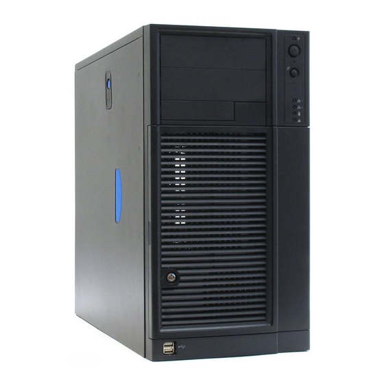
Intel SC5299BRP Manuals
Manuals and User Guides for Intel SC5299BRP. We have
1
Intel SC5299BRP manual available for free PDF download: Technical Product Specification
Intel SC5299BRP Technical Product Specification (154 pages)
Entry Server Chassis
Brand:
Intel
| Category:
Chassis
| Size: 1.56 MB
Table of Contents
Revision History
2
Table of Contents
4
1 Product Overview
16
Intel® Entry Server Chassis SC5299-E Design Features
16
Chassis Views
18
Figure 1. Front Closed Chassis View of Intel
18
Figure 2. Rear Closed Chassis View of Intel Entry Server Chassis SC5299-E
19
Figure 3. Front Internal Chassis View of Intel
20
Figure 4. Rear Internal Chassis View of Intel
20
System Color
21
Chassis Security
21
I/O Panel
21
Rack and Cabinet Mounting Option
21
Figure 5. ATX 2.2 I/O Aperture
21
Front Bezel Features
22
Peripheral Bays
22
2 Power Sub-System
23
420-Watt Power Supply
23
Mechanical Overview
24
Figure 6. Mechanical Drawing for Power Supply Enclosure
24
Airflow and Temperature
25
Output Cable Harness
25
Table 2. Environmental Requirements
25
Figure 7. Output Cable Harness for 420-W Power Supply
26
Table 3. Cable Lengths
27
Table 4. P1 Baseboard Power Connector
27
Table 5. P2 Processor Power Connector
28
Table 6. P3-P6, P8-P9 Peripheral Connectors
28
AC Input Requirements
29
Table 7. P10 Right-Angle SATA Power Connector
29
Table 8. AC Input Rating
29
DC Output Specifications
31
Table 9. AC Line Sag Transient Performance
31
Table 10. AC Line Surge Transient Performance
31
Table 11. Load Ratings
32
Table 12. Voltage Regulation Limits
33
Table 13. Transient Load Requirements
33
Table 14. Capacitive Loading Conditions
34
Table 15. Ripple and Noise
34
Figure 8. Output Voltage Timing
35
Table 16. Output Voltage Timing
35
Table 17. Turn On/Off Timing
35
Protection Circuits
36
Table 18. over Voltage Protection Limits
37
Table 19. PSON# Signal Characteristic
38
Table 20. PWOK Signal Characteristics
38
550-Watt Power Supply
39
Mechanical Outline
40
Figure 9. Mechanical Drawing for Power Supply Enclosure
40
Figure 10. System Airflow Impedance
41
Table 21. Acoustic Requirements
41
AC Input Voltage Requirements
42
Table 22. Environmental Requirements
42
Table 23. AC Input Rating
42
Table 24. AC Line Sag Transient Performance
43
Table 25. AC Line Surge Transient Performance
43
Table 26. Performance Criteria
43
Table 27. AC Line Dropout/Holdup
45
Efficiency
46
DC Output Specifications
46
Table 28. Efficiency
46
Table 29. Cable Lengths
47
Table 30. P1 Main Power Connector
47
Table 31. P2 Processor Power Connector
48
Table 32. P12 Baseboard Power Connector
48
Table 33. P3, P4, P6, P7, P8, P9 Peripheral Power Connectors
48
Table 34. P5 Floppy Power Connector
49
Table 35. P10 SATA Power Connectors
49
Table 36. P11 SATA Power Connectors
49
Table 37. Load Ratings
50
Table 38. Power on Load Ratings
51
Table 39. Power on Voltage Regulation Limits
51
Table 40. Voltage Regulation Limits
52
Table 41. Transient Load Requirements
52
Table 42. Capacitive Loading Conditions
53
Table 43. Ripple and Noise
54
Table 44. Output Voltage Timing
54
Figure 11. Output Voltage Timing
55
Table 45. Turn On/Off Timing
55
Protection Circuits
56
Figure 12. Turn On/Off Timing (Power Supply Signals)
56
Table 46. Over-Current Protection
57
Table 47. Over-Voltage Protection Limits
57
Control and Indicator Functions
58
Table 48. PSON Signal Characteristic
58
Table 49. PWOK Signal Characteristics
59
650-W Power Supply Module
60
Mechanical Overview
60
AC Input Requirements
61
Table 50. Acoustic Requirements
61
Table 51. Thermal Requirements
61
Table 52. AC Input Rating
62
Table 53. AC Line Sag Transient Performance
62
Table 54. AC Line Surge Transient Performance
63
Table 55. Performance Criteria
63
Table 56. Holdup Requirements
64
DC Output Specification
66
Table 57. Edge Finger Power Supply Connector Pin-Out
66
Table 58. Power Supply Module Load Ratings
68
Table 59. Voltage Regulation Limits
68
Table 60. Transient Load Requirements
68
Table 61. Capacitive Loading Conditions
69
Table 62. Ripple and Noise
69
Figure 13. Output Voltage Timing
70
Figure 15. Output Voltage Timing
70
Table 63. Output Voltage Timing
70
Protection Circuits
72
Table 65. Over-Current Protection (OCP)
72
Control and Indicator Functions
73
Table 66. Over-Voltage Protection Limits
73
Table 67. PSON Signal Characteristic
74
Table 68. PSKILL Signal Characteristics
75
Table 69. PWOK Signal Characteristics
75
Smbus Monitoring Interface
76
Table 70. LED Indicators
76
650-W Power Distribution Board (PDB)
77
Table 71. Smbus Device Addressing
77
Figure 14. Mechanical Drawing for Dual (1+1 Configuration) Power Supply Enclosure
78
Mechanical Overview
78
Table 72. Environmental Requirements
78
DC Output Specification
79
Table 73. Edge Finger Power Supply Connector Pin-Out
79
Table 74. Cable Lengths
80
Table 75. P1 Baseboard Power Connector
81
Table 76. P2 Processor Power Connector
82
Table 77. P13 12V4 Power Connector
82
Table 78. Power Signal Connector
82
Table 79. Peripheral Power Connectors
83
Table 80. Floppy Power Connector
83
Table 81. 12V4 Power Connector
83
Table 82. SATA Power Connector
84
Table 83. +12V Outputs Load Ratings
84
DC/DC Converters Dynamic Loading
85
Table 84. DC/DC Converter Load Ratings
85
Table 85. Voltage Regulation Limits
85
Table 86. Transient Load Requirements
86
Table 87. Capacitive Loading Conditions
86
Table 88. Ripple and Noise
87
Table 89. Output Voltage Timing
87
Table 90. Turn On/Off Timing
88
Figure 16. Turn On/Off Timing (Power Supply Signals)
89
Table 1. Intel
89
Protection Circuits
90
Table 91. Over-Current Protection Limits/240Va Protection
90
Control and Indicator Functions (Hard-Wired)
91
Table 92. Over-Voltage Protection (OVP) Limits
91
Table 93. PSON Signal Characteristics
92
Table 94. PWOK Signal Characteristics
93
Table 95. Smbalert# Signal Characteristics
93
PSMI (Power Supply Monitoring Interface)
94
Table 96. Device Address Locations
94
670-W Power Supply
95
Mechanical Overview
95
Figure 17. Mechanical Drawing of the 670-W Power Supply Enclosure
96
Acoustic Requirements
97
Airflow Requirements
97
Temperature Requirements
97
Table 97. Sound Power Requirement
97
Table 98. Thermal Requirements
97
Output Wire Harness Drawing
98
Table 99. Cable Lengths
98
Figure 18. Output Harness for 670-W Power Supply
99
Power Connectors
100
Table 100. P1 Baseboard Power Connector
100
Table 101. P2 Processor Power Connector
101
Table 102. Power Signal Connector
101
Table 103. 12V4 Power Connector
102
Table 104. PCI Express Connector
102
Table 105. Peripheral Power Connectors
102
Table 106. P7 Right-Angle Peripheral Power Connector
103
Table 107. P5 Floppy Power Connector
103
Table 108. P12 Right-Angle SATA Power Connector
103
AC Input Requirements
104
Table 109. P13 SATA Power Connector
104
Table 110. AC Input Rating
105
Table 111. Efficiency
105
Table 112. AC Line Dropout/Holdup
105
Table 113. Performance Criteria
107
Table 114. AC Line Sag Transient Performance
108
Table 115. AC Line Surge Transient Performance
108
DC Output Specifications
109
Table 116. Load Ratings
110
Table 117. Voltage Regulation Limits
111
Table 118. Transient Load Requirements
111
Table 119. Capacitive Loading Conditions
111
Table 120. Pre-Set Lighter Load
112
Table 121. Pre-Set Lighter Voltage Regulation Limits
113
Table 122. Ripple and Noise
113
Figure 19. Output Voltage Timing
114
Table 123. Output Voltage Timing
114
Table 64. Turn On/Off Timing
115
Table 124. Turn On/Off Timing
115
Protection Circuits
116
Figure 20. Turn On/Off Timing (Power Supply Signals)
116
Table 125. Over-Current Protection (OCP)/240VA
116
Table 126. Over-Voltage Protection Limits
117
Control and Indicator Functions
118
Table 127. PSON Signal Characteristic
118
Table 128. PWOK Signal Characteristics
119
3 Chassis Cooling
120
Fan Configuration
120
Server Board Fan Control
120
Cooling Solution
121
Figure 21. Cooling Fan Configuration
121
4 Peripheral and Hard Drive Support
122
3.5-In Peripheral Drive Bay
122
5.25-In Peripheral Drive Bays
122
Figure 22. Drive Bay Locations for Intel
122
Hard Disk Drive Bays
123
Fixed Hard Drive Bay
123
Figure 23. 6-HDD Fixed Drive Bay, Rear Isometric View
123
SAS Non-Expander/Serial-ATA (SATA) Hot Swap Back Plane (HSBP)
124
Figure 24. Intel
125
Figure 25. Intel
127
Table 129. I C Bus Addressing
127
Table 130. I C Bus Loading
127
Connection Diagram
127
Table 131. GEM424* Controller GPIO Assignment
128
Table 132. LED Function
130
Table 133. 7-Pin SATA Connector Pin-Out
130
Table 134. 22-Pin SATA Connector Pin-Out
130
Table 135. Power Connector Pin-Out
131
Table 136. IPMB Header Pin-Out
132
Table 137. SATA Host I
132
Figure 26. Intel Entry Server Chassis SC5299-E 6HDD SATA Hot Swap Backplane Board Layout
133
Table 138. SATA Hot-Swap Backplane Connector Specifications
133
5 Standard Control Panel
135
Control Panel
135
Figure 27. Panel Controls and Indicators
135
Table 139. Control Panel LED Functions
136
6 Intel® Local Control Panel
137
Figure 28. SKU3 - Pedestal Server Application
137
Internal Control Panel Headers
138
Table 140. IPMI Header
138
7 System Interconnection
139
Signal Definitions
139
Chassis Internal Cables
139
Control Panel Cable
139
USB Cable
139
Fan Connector
139
Chassis Intrusion Cable
139
Server Board Internal Cables
139
Accessory Cables
139
I/O Panel Connectors
139
Spares and Accessories
140
8 Supported Intel® Server Boards
141
9 Regulatory, Environmentals, and Specifications
142
Product Regulatory Compliance
142
Product Safety Compliance
142
Product EMC Compliance - Class a Compliance
142
Product Ecology Requirements
143
Certifications/Registrations/Declarations
143
Product Regulatory Compliance Markings
144
Electromagnetic Compatibility Notices
145
FCC Verification Statement (USA)
145
ICES-003 (Canada)
145
Europe (CE Declaration of Conformity)
146
Japan EMC Compatibility
146
BSMI (Taiwan)
146
RRL (Korea)
146
Regulated Specified Components
147
End of Life/Product Recycling
147
Restriction of Hazardous Substances (Rohs) Compliance
147
Replacing the Back up Battery
148
System-Level Environmental Limits
148
BTU Information
149
Table 141. System Office Environment Summary
149
Table 142. System BTU Information Table
149
Serviceability and Availability
150
Table 143. Mean Time to Repair Estimate
150
Table 144. Intel
151
Advertisement
Advertisement
Related Products
Intel SC5299BRPNA
Intel SC5299DPNA
Intel SC5299WS
Intel SC5299UP - Server Chassis Tower
Intel SC5299-E DP
Intel SC5299-E WS
Intel SC5299-E BRP
Intel SC5299-E UP
Intel SC5299-E Series
Intel SC5275-E WS
Intel Categories
Motherboard
Computer Hardware
Server
Server Board
Desktop
More Intel Manuals
Login
Sign In
OR
Sign in with Facebook
Sign in with Google
Upload manual
Upload from disk
Upload from URL