Sign In
Upload
Manuals
Brands
Intel Manuals
Server
S2600WF Series
Intel S2600WF Series Manuals
Manuals and User Guides for Intel S2600WF Series. We have
5
Intel S2600WF Series manuals available for free PDF download: Configuration Manual, Technical Product Specification
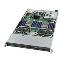
Intel S2600WF Series Technical Product Specification (140 pages)
Server Board Product Family
Brand:
Intel
| Category:
Server
| Size: 8.01 MB
Table of Contents
Table of Contents
5
1 Introduction
13
Table 1. Reference Documents
13
Intel Server Board Use Disclaimer
14
Product Errata
14
2 Server Board Family Overview
15
Figure 1. Intel® Server Board S2600WF
15
Figure 2. Intel® Server Board S2600WF with Available Onboard Options
16
Server Board Family Feature Set
17
Table 2. Intel® Server Board S2600WF Product Family Feature Set
17
Figure 3. Server Board Component/Feature Identification
19
Server Board Component/Feature Identification
19
Figure 4. Intel® Server Board S2600WF External I/O Connector Layout
20
Figure 5. Intel® Light Guided Diagnostics - DIMM Fault Leds
20
Figure 6. Intel® Light Guided Diagnostic - LED Identification
21
Figure 7. Board Configuration and Recovery Jumpers
22
Figure 8. Intel® Server Board S2600WF Primary Side Keepout Zone
23
Server Board Mechanical Drawings
23
Figure 9. Intel® Server Board S2600WF Hole and Component Positions
24
Figure 10. Intel® Server Board S2600WF Secondary Side Keepout Zone
25
Figure 11. Intel® Server Board S2600WF Primary Side Height Restrictions
26
Figure 12. Intel® Server Board S2600WF Product Family Architectural Block Diagram
27
Product Architecture Overview
27
System Software Stack
28
Figure 13. Intel® Server Board S2600WFQ Architectural Block Diagram
28
Hot Keys Supported During POST
29
Table 3. POST Hot Keys
29
Field Replaceable Unit (FRU) and Sensor Data Record (SDR) Data
31
3 Processor Support
33
Processor Socket and Processor Heat Sink Module (PHM) Assembly
33
Figure 14. Processor Heat Sink Module (PHM) Components and Processor Socket Reference Diagram
33
Figure 15. Processor Attached to the Processor Heat Sink Installation
34
Figure 16. PHM to CPU Socket Orientation and Alignment Features
34
Processor Thermal Design Power (TDP) Support
35
Figure 17. Processor Socket Assembly and Protective Cover
35
Intel® Xeon® Processor Scalable Family Overview
36
Table 4. Intel® Xeon® Processor Scalable Family Feature Comparison
36
Supported Technologies
37
Intel® Xeon® Processor Scalable Family with Integrated Intel® Omni-Path Fabric
39
Table 5. Intel® Xeon® Processor Scalable Family with Integrated Intel® OP HFI Features
39
Figure 18. Intel® OP HFI Connector Location
40
Figure 19. Multi-Chip Package (MCP)
40
Figure 20. Dual Processor Configurations with One or Two Fabric Processors
41
Intel®Omni-Path IFT Carrier Accessory Kits
41
Figure 21. Intel® Omni-Path IFT Carrier Accessory Kit Components
42
Figure 22. Server Board Sideband Connectors
42
Figure 23. IFT Carrier Board - Rear View
43
Table 6. IFT Carrier LED Functionality
43
Table 7. Power Level Classification for QSFP+ Modules
43
Table 8. Supported Processor Mixing - Fabric Vs Non-Fabric Processors
43
Processor Population Rules
44
Processor Initialization Error Summary
44
Table 9. Mixed Processor Configurations Error Summary
45
4 System Memory
47
Memory Subsystem Architecture
47
Figure 24. Memory Subsystem Architecture
47
Supported Memory
48
Memory Slot Identification and Population Rules
48
Figure 25. Intel® Server Board S2600WF Memory Slot Layout
48
Table 10.DDR4 RDIMM and LRDIMM Support
48
DIMM Population Guidelines for Best Performance
50
Figure 26. DIMM Population Diagram
50
Memory RAS Features
51
Table 11. Memory RAS Features
51
DIMM Populations Rules and BIOS Setup for Memory RAS
52
5 Pcie* Support
53
Pcie* Enumeration and Allocation
53
Non-Transparent Bridge
53
Table 12. CPU - Pcie* Port Routing
53
Figure 27. Two Systems Connected through an NTB
54
6 System I/O
55
Intel® Quickassist Technology (Intel® QAT) Support
55
Pcie* Add-In Card Support
56
Figure 28. Intel® QAT Cable
56
Figure 29. Pcie* Add-In Card Support
57
Riser Slot #1 and Riser Slot #2 Riser Card Options
57
Table 13. Riser Slot #1 Pcie* Root Port Mapping
57
Table 14. Riser Slot #2 Pcie* Root Port Mapping
57
Table 15. Riser Slot #3 Pcie* Root Port Mapping
57
Figure 30. 1U One-Slot Pcie* Riser Card (Ipc - F1UL16RISER3APP)
58
Figure 31. 2U Three-Slot Pcie* Riser Card (Ipc - A2UL8RISER2)
58
Table 16. One-Slot Pcie* Riser Card Slot Description
58
Table 17. Three-Slot Pcie* Riser Card Slot Description
58
Figure 32. 2U Two-Slot Pcie* Riser Card (Ipc - A2UL16RISER2)
59
Figure 33. Low Profile Riser Card (Ipc - A2UX8X4RISER)
59
Intel® Ethernet Network Adapter for OCP* Support
59
Riser Slot #3 Riser Card Option (Ipc - A2UX8X4RISER)
59
Table 18. Two-Slot Pcie* Riser Card Slot Description
59
Table 19. Low Profile Riser Card Slot Description
59
Figure 34. Intel® Ethernet Network Adapter for OCP* Connector
60
Table 20. Supported Intel® Ethernet Network Adapters for OCP
60
Intel® Integrated RAID Module Support
61
Onboard Storage Subsystem
61
M.2 SSD Support
61
Figure 35. Intel® Integrated RAID Module
61
Figure 36. M.2 Storage Device Connectors
62
Onboard Pcie* Oculink Connectors
63
Intel® Volume Management Device (Intel® VMD) for Nvme
63
Figure 37. Onboard Oculink Connectors
63
Figure 38. Nvme* Storage Bus Event/Error Handling
63
Figure 39. Intel® VMD Support Disabled in BIOS Setup
65
Figure 40. Intel® VMD Support Enabled in BIOS Setup
65
Intel® Virtual RAID on Chip (Intel® VROC) for Nvme
66
Figure 41. Intel® VROC Basic Architecture Overview
66
Onboard SATA Support
67
Figure 42. Intel® VROC Upgrade Key
67
Table 21. Intel® VROC Upgrade Key Options
67
Figure 43. Onboard SATA Port Connector Identification
68
Table 22. SATA and Ssata Controller Feature Support
68
Onboard SATA RAID Options
69
Table 23. SATA and Ssata Controller BIOS Setup Utility Options
69
Figure 44. BIOS Setup Mass Storage Controller Configuration Screen
70
Figure 45. Intel® ESRT2 SATA RAID-5 Upgrade Key (Ipn - RKSATA4R5)
71
Rear External RJ45 Connector Overview
72
RJ45 Dedicated Management Port
72
Figure 46. Rear External RJ45 Connectors
72
Figure 47. RJ45 Connector Leds
72
Table 24. External RJ45 NIC Port LED Definition
72
RJ45 Network Interface Connectors (Intel® Server Board S2600WFT Only)
73
Serial Port Support
73
Figure 48. RJ45 Serial-A Pin Orientation
73
Table 25.Serial-A Connector Pinout
73
Figure 49. J4A2 Jumper Block for Serial-A Pin 7 Configuration
74
Figure 50. Serial-B Connector (Internal)
74
Table 26. Serial-B Connector Pinout
74
USB Support
75
External USB 3.0 Connector
75
Internal USB 2.0 Type-A Connector
75
Front Panel USB 3.0 Connector
75
Figure 51. External USB 3.0 Ports
75
Figure 52. Internal USB 2.0 Type-A Connector
75
Front Panel USB 2.0 Connector
76
Figure 53. Front Panel USB 3.0 Connector
76
Table 27. Front Panel USB 2.0/3.0 Connector Pinout ("FP_USB_2.0/ 3.0")
76
Video Support
77
Figure 54. Front Panel USB 2.0 Connector
77
Table 28. Front Panel USB 2.0 Connector Pinout ("FP_USB_2.0_5-6 ")
77
Table 29. Supported Video Resolutions
77
Figure 55. Rear External Video Connector
78
Figure 56. Front Panel Video Connector
78
Onboard Video Connectors
78
Table 30. Front Panel Video Connector Pinout ("FP VIDEO")
78
Dual Monitor Support
79
Onboard Video and Add-In Video Adapter Support
79
7 Onboard Connector/Header Pinout Definition
80
Power Connectors
80
Main Power
80
Figure 57. "MAIN PWR 1" and "MAIN PWR 2" Connectors
80
Table 31. Main Power (Slot 1) Connector Pinout ("MAIN PWR 1")
81
Table 32. Main Power (Slot 2) Connector Pinout ("MAIN PWR 2")
81
Hot Swap Backplane Power Connector
82
Figure 58. Hot Swap Backplane Power Connector
82
Table 33. Hot Swap Backplane Power Connector Pinout ("HSBP PWR")
82
Riser Card Supplemental 12-V Power Connectors
83
Figure 59. Riser Slot Auxiliary Power Connectors
83
Table 34. Riser Slot Auxiliary Power Connector Pinout ("OPT_12V_PWR")
83
Peripheral Power Connector
84
Figure 60. High Power Add-In Card 12-V Auxiliary Power Cable Option
84
Figure 61. Peripheral Power Connector
84
Table 35. Peripheral Drive Power Connector Pinout ("Peripheral_Pwr")
84
Front Control Panel Headers and Connectors
85
Figure 62. Front Control Panel Connectors
85
Figure 63. Example Front Control Panel View (for Reference Purposes Only)
85
Table 36. Front Panel Control Button and LED Support
85
Front Panel LED and Control Button Features Overview
86
Table 37. 30-Pin Front Panel Connector Pinouts
86
Table 38. Power/Sleep LED Functional States
86
Table 39. NMI Signal Generation and Event Logging
87
System Fan Connectors
88
Figure 64. Dual-Rotor Fixed Mount Fan Pin Connector Orientation
88
Figure 65. Hot Swap Fan Connector Pin Orientation
88
Table 40. Dual-Rotor Fixed Mount Fan Connector Pinout
88
Table 41. Hot Swap Fan Connector Pinout
88
Management Connectors
89
Figure 66. Fan Connector Locations
89
Figure 67.Hot Swap Backplane Connector Locations
89
Table 42. Hot Swap Backplane I C Connector - SMBUS 3-Pin (J5C3)
89
Table 43. Hot Swap Backplane I 2 C Connector - SMBUS 4-Pin (J1K1)
90
Table 44. IPMB - SMBUS 4-Pin (J1C3)
90
8 Basic and Advanced Server Management Features
91
Figure 68. Intel® RMM4 Lite Activation Key Installation
91
Table 45. Intel® Remote Management Module 4 (Intel® RMM4) Options
91
Table 46. Basic and Advanced Server Management Features Overview
91
Dedicated Management Port
92
Embedded Web Server
92
Figure 69. Dedicated Managment Port
92
Advanced Management Feature Support
94
Keyboard, Video, Mouse (KVM) Redirection
94
Media Redirection
95
Remote Console
96
Performance
96
9 Light Guided Diagnostics
97
Figure 70. Onboard Diagnostic and Fault LED Placement
97
System ID LED
98
System Status LED
98
Figure 71.DIMM Fault LED Placement
98
BMC Boot/Reset Status LED Indicators
99
Table 47. System Status LED States
99
Table 48. BMC Boot/Reset Status LED Indicators
99
Post Code Diagnostic Leds
100
Fan Fault Leds
100
Memory Fault Leds
100
CPU Fault Leds
100
10 System Security
101
10.1 Password Protection
101
Password Setup
101
Figure 72. BIOS Setup Security Tab
101
System Administrator Password Rights
102
Authorized System User Password Rights and Restrictions
102
10.2 Front Panel Lockout
103
10.3 Trusted Platform Module (TPM) Support
103
TPM Security BIOS
103
Physical Presence
104
TPM Security Setup Options
104
10.4 Intel® Trusted Execution Technology
104
11 Reset and Recovery Jumpers
105
11.1 BIOS Default Jumper Block
105
Figure 73. Reset and Recovery Jumper Block Location
105
11.2 Password Clear Jumper Block
106
11.3 Intel® Management Engine (Intel® ME) Firmware Force Update Jumper Block
106
11.4 BMC Force Update Jumper Block
107
11.5 BIOS Recovery Jumper
107
12 Platform Management
109
12.1 Management Feature Set Overview
109
IPMI 2.0 Features Overview
109
Non-IPMI Features Overview
109
12.2 Platform Management Features and Functions
111
Power Subsystem
111
Advanced Configuration and Power Interface (ACPI)
111
Table 49. Power Control Sources
111
Table 50. ACPI Power States
111
System Initialization
112
Watchdog Timer
112
System Event Log (SEL)
112
12.3 Sensor Monitoring
113
Sensor Re-Arm Behavior
113
Thermal Monitoring
113
Standard Fan Management
114
Memory Thermal Management
116
Figure 74. High-Level Fan Speed Control Process
116
Power Management Bus (Pmbus*)
117
Component Fault LED Control
118
Table 51. Component Fault Leds
118
Appendix A. Integration and Usage Tips
119
Appendix B. POST Code Diagnostic LED Decoder
120
Figure 75. Onboard POST Diagnostic LED Location and Definition
120
Table 52. POST Progress Code LED Example
120
B.1. Early POST Memory Initialization MRC Diagnostic Codes
121
Table 53. MRC Progress Codes
121
Table 54. MRC Fatal Error Codes
122
B.2. BIOS POST Progress Codes
123
Table 55. POST Progress Codes
123
Appendix C. POST Code Errors
126
Table 56. POST Error Messages and Handling
127
C.1. POST Error Beep Codes
133
Table 57. POST Error Beep Codes
133
Table 58. Integrated BMC Beep Codes
133
Appendix D. Statement of Volatile Memory Components
134
Table 59. Volatile and Non-Volatile Components
135
Appendix E. Supported Intel® Server Systems
136
E.1. Intel® Server System R1000WF Product Family
136
Figure 76. Intel® Server System R1000WF Product Family
136
Table 60. Intel® Server System R1000WF Product Family Feature Set
137
E.2. Intel® Server System R2000WF Product Family
138
Figure 77. Intel® Server System R2000WF Product Family
138
Table 61. Intel® Server System R2000WF Product Family Feature Set
138
Appendix F. Glossary
140
Advertisement
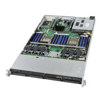
Intel S2600WF Series Configuration Manual (142 pages)
Server Board/Chassis/Server System
Brand:
Intel
| Category:
Server
| Size: 9.8 MB
Table of Contents
Table of Contents
6
1 Intel® Server Family Overview
13
Figure 1. Intel® Server S2600WF Product Family Overview
13
Configuration Overview
14
Processor Support
15
Figure 2. Intel® Xeon® Processor Scalable Family Generation Identification
15
Table 1. 1 St Gen Intel® Xeon® Processor Scalable Family Feature Comparison
16
Table 2. 1 St Gen Intel® Xeon® Processor Scalable Family with Integrated Intel® Omni-Path Fabric Feature Comparison
17
Table 3. 2 Nd Gen Intel® Xeon® Processor Scalable Family Feature Comparison
18
Memory Support
19
System Configuration Notes
19
Additional Information and Software
20
Table 4. Product Family Reference Collaterals
20
Figure 3. Intel® Server Board S2600WF Onboard Features
21
Intel® Server Board S2600WF Product Family
21
Table 5. Intel® Server Board S2600WF Product Family Features
22
Figure 4. Intel® Server Board S2600WFTF Onboard Features
24
Intel® Server Board S2600WFTF Product Family
24
Table 6. Intel® Server Board S2600WFTF Product Family Features
25
Figure 5. Intel® Server System R1000WF Feature Set Identification
27
Intel® Server System R1000WF Product Family
27
Figure 6. 1U, 3.5" X 4 Drive Configuration (Intel® Server System R1304Xxx)
28
Figure 7. 1U, 2.5" X 8 Drive Configuration (Intel® Server System R1208Wfxxx)
28
Figure 8. 1U System Back Panel
28
Table 7. Intel® Server System R1000WF Product Family Features
29
Figure 9. Intel® Server System R2000WF Feature Set Identification
30
Intel® Server System R2000WF Product Family
30
Figure 10. 2U, no Drive Bays, Chassis Only Building Block (Intel® Server Chassis R2000Wfxxx)
31
Figure 11. 2U, 3.5" X 8 Drive Configuration (Intel® Server System R2308Wfxxx)
31
Figure 12. 2U, 3.5" X 12 Drive Configuration (Intel® Server System R2312Wfxxx - Storage Configuration)
31
Figure 13. 2U, 2.5" X 8 Drive Configuration (Intel® Server System R2208Wfxxx)
32
Figure 14. 2U, 2.5" X 16 Drive Configuration (Intel® Server System R2208Wfxxx + 8 Drive Accessory Kit)
32
Figure 15. 2U, 2.5" X 24 Drive Configuration (Intel® Server System R2224Wfxxx - Storage Configuration)
32
Figure 16. 2U System Back Panel with Optional 2 X 2.5" Hot Swap Drive Bay
33
Table 8. Intel® Server System R2000WF Product Family Features
33
Figure 20. Intel® Server System R2000WFTF Feature Set Identification
35
Intel® Server System R2000WFTF Product Family
35
Figure 21. 2U, 2.5" X 8 Drive Configuration (Intel® Server System Lfrb2208Wftfxxx)
36
Figure 22. 2U, 3.5" X 12 Drive Configuration (Intel® Server System Lfrb2312Wftfxxx - Storage Configuration)
36
Figure 23. System Back Panel for Intel® Server System R2000WFTF with Optional 2 X 2.5" Hot-Swap Drive Bay
36
Table 10. Intel® Server System R2000WFTF Product Family Features Table
37
Available Server Board, Chassis, and System SKU Summary
39
Table 11. Server Board Product Family Summary
39
Table 12. Server Chassis (KDK) Product Family Summary
39
Table 13. Server System (BIK) Product Family Summary
40
2 Server Building Block Options
41
Figure 24. Illustration of Building Block Options
41
Intel® Server Board S2600WF Product Family Options
43
Table 14. Intel® Server Board S2600WF Product Family Options
43
Figure 25. Intel® Server Chassis Options
45
Intel® Server Chassis Product Family Options
45
Table 15. Intel® Server Chassis R1304WFXXX Product Specifications and Configuration Requirements
46
Table 16. Intel® Server Chassis R1208WFXXX Product Specifications and Configuration Requirements
47
Table 17. Intel® Server Chassis R2000WFXXX Product Specifications and Configuration Requirements
48
Table 18. Intel® Server Chassis R2312WFXXX Product Specifications and Configuration Requirements
49
3 Server System Configurations
50
Figure 26. Intel® Server System Options
50
Figure 27. Intel® Server System R1000WF Product Family
51
Intel® Server System R1000WF Product Family - (1U Rack Mount System)
51
Table 19. Intel® Server System R1304WF0YS Product Specifications and Configuration Requirements
52
Table 20. Intel® Server System R1304WF0YSR Product Specifications and Configuration Requirements
53
Table 21. Intel® Server System R1304WFTYS Product Specifications and Configuration Requirements
54
Table 22. Intel® Server System R1304WFTYSR Product Specifications and Configuration Requirements
55
Table 23. Intel® Server System R1208WFTYS Product Specifications and Configuration Requirements
56
Table 24. Intel® Server System R1208WFTYSR Product Specifications and Configuration Requirements
57
Table 25. Intel® Server System R1208WFQYSR Product Specifications and Configuration Requirements
58
Intel® Server System R2000WF Product Family - (2U Rack Mount System)
59
Table 29. Intel® Server System R2308WFTZS Product Specifications and Configuration Requirements
60
Table 30. Intel® Server System R2308WFTZSR Product Specifications and Configuration Requirements
61
Table 31. Intel® Server System R2208WF0ZS Product Specifications and Configuration Requirements
62
Table 32. Intel® Server System R2208WF0ZSR Product Specifications and Configuration Requirements
63
Table 33. Intel® Server System R2208WFTZS Product Specifications and Configuration Requirements
64
4 Sas/Sata/Nvme* Data Cable Guide
82
Cable Connector Types
83
1U/2U Server System Sas/Sata/Nvme* Cable Kits
84
Cable Kit Product Code Decoder Examples
85
Cable Kit Order Information
85
Cable Recommendations
90
X 3.5" - R1304Wfxxx SAS/SATA Data Cable Guide
91
X 2.5" - R1208Wfxxx Sas/Sata/Nvme* Data Cable Guide
92
X 3.5" - R2308Wfxxx SAS/SATA Data Cable Guide
93
Figure 28. R2308Wfxxx SAS/SATA Backplane (no Nvme* Support)
93
2U 12 X 3.5 - R2312Wfxxx Sas/Sata/Nvme* Data Cable Guide
94
12 X 3.5" - R2312Wfxxx Sas/Sata/Nvme* Data Cable Guide (with no SAS Expander)
94
Figure 29. R2312Wfxxx SAS/SATA Backplane
94
12 X 3.5" - R2312Wtxxx Sas/Sata/Nvme* Data Cable Guide (with SAS Expander)
95
Figure 30. SAS 3.0 12 Gb/S Expander
95
2.5" Front Mount Drive Bay Cable Guide
97
Figure 31.2.5" Front Mount Drive Bay and 8 X 2.5" Combo Hot-Swap Backplane
97
8X2.5" Drive Bay Module #1 - Cable Guide (with no SAS Expander)
98
8X2.5" Drive Bay Module #2 - Cable Guide (with no SAS Expander)
101
8X2.5" Drive Bay Module #3 - Cable Guide (with no SAS Expander)
103
2.5" Front Mount Drive Configurations - Cable Guide (with SAS Expander)
106
Figure 32. SAS Expander Module Identification and Placement
106
5 U/2U System Optional Accessories
108
2U Rear Mount Hot Swap Drive Bay Accessory Kits
108
2U Pcie* Riser Card Accessory/Spare FRU Options
109
Riser Card Options
109
2U Riser Card Options
110
8X2.5" Drive Bay Module Options
111
Intel® Ethernet Network Adapters for OCP
113
Intel® RAID Add-In Cards, Modules, and Accessories
115
Power Supply Modules and Power Cords
126
2U Rack Mount Kits
128
6 U/2U Miscellaneous Accessory Options
131
7 U/2U Spare and Replacement Parts (Frus)
137
8 Intel® Visual Compute Accelerators
140
Appendix A. Glossary
141
Intel S2600WF Series Configuration Manual (127 pages)
Server Board/Chassis/System
Brand:
Intel
| Category:
Server
| Size: 8.57 MB
Table of Contents
Table of Contents
7
1 Intel Server Family Overview
11
Table 1. Intel® Xeon® Processor Scalable Family - Feature Comparison Table
12
Table 2. Intel® Xeon® Processor Scalable Family W/ Integrated Intel® Omni-Path Fabric - Features Table
13
Table 6. Intel® Server System R1000WF Product Family Features Table
23
Figure 14. 2U System Back Panel with Optional 2 X 2.5" Hot Swap Drive Bay
27
Table 7. Intel® Server System R2000WF Product Family Features Table
27
Available Server Board, Chassis, and System SKU Summary
29
Table 8. Server Board Product Family Summary
29
Table 9. Server Chassis (KDK) Product Family Summary
29
Table 10. Server System (BIK) Product Family Summary
30
Figure 15. Intel® Server System R2000WFTF Feature Set Identification
32
Intel® Server System R2000WFTF Product Family
32
Figure 16. 2U, 2.5" X 8 Drive Configuration (Intel® Server System Lfrb2208Wftfxxx)
33
Figure 18. 2U System Back Panel with Optional 2 X 2.5" Hot Swap Drive Bay
33
Table 11. Intel® Server System R2000WFTF Product Family Features Table
34
Table 3. Product Family Reference Collaterals
14
Figure 1. Intel® Server Board S2600WF Onboard Features
15
Intel Server Board S2600WF Product Family
15
Table 4. Server Board Product Family Features Table
16
Figure 2. Intel® Server Board S2600WFTF Onboard Features
18
Intel Server Board S2600WFTF Product Family
18
Table 5. Intel® Server Board S2600WFTF Product Family Features Table
19
Figure 3. Intel® Server System R1000WF Feature Set Identification
21
Intel Server System R1000WF Product Family
21
Figure 4. 1U, 3.5" X 4 Drive Configuration (Intel® Server System R1304Xxx)
22
Figure 5. 1U, 2.5" X 8 Drive Configuration (Intel® Server System R1208Wfxxx)
22
Figure 6. 1U System Back Panel
22
Figure 7. Intel® Server System R2000WF Feature Set Identification
24
Intel® Server System R2000WF Product Family
24
Figure 10. 2U, 3.5" X 12 Drive Configuration (Intel® Server System R2312Wfxxx - Storage Configuration)
25
Figure 8. 2U, no Drive Bays, Chassis Only Building Block (Intel® Server Chassis R2000Wfxxx)
25
Figure 9. 2U, 3.5" X 8 Drive Configuration (Intel® Server System R2308Wfxxx)
25
Figure 11. 2U, 2.5" X 8 Drive Configuration (Intel® Server System R2208Wfxxx)
26
Figure 12. 2U, 2.5" X 16 Drive Configuration (Intel® Server System R2208Wfxxx + 8 Drive Accessory Kit)
26
Figure 13. 2U, 2.5" X 24 Drive Configuration (Intel® Server System R2224Wfxxx - Storage Configuration)
26
2 Server Building Block Options
36
Intel® Server Board S2600WF Product Family Options
37
Table 12. Intel® Server Board S2600WF Product Family Options
37
Intel® Server Chassis Product Family Options
39
Intel Power Supply Modules and Power Cords
42
3 Server System Configuration
43
Intel® Server System R1000WF Product Family Skus - (1U Rack Mount System)
44
Figure 19. Intel® Server System R1000WF Product Family
44
Intel® Server System R2000WF Product Family Skus - (2U Rack Mount System)
48
4 SAS / SATA / Nvme Data Cable Guide
64
Cable Connector Types
65
1U / 2U Server System SAS / SATA / Nvme Cable Kits
67
Table 13.Data Cable Connector Identification
67
Table 14. SATA / SAS / Nvme Data Cable Kit Description and Order Information
68
X 3.5" - R1304Wfxxx SAS / SATA Data Cable Guide
74
X 2.5" - R1208Wfxxx SAS / SATA / Nvme Data Cable Guide
75
X 3.5" - R2308Wfxxx SAS / SATA Data Cable Guide
76
Figure 20. R2308Wfxxx SAS / SATA Backplane
76
12 X 3.5 - R2312Wfxxx SAS / SATA / Nvme Data Cable Guide
77
12 X 3.5" - R2312Wfxxx SAS / SATA / Nvme Data Cable Guide (with no SAS Expander)
77
Figure 21. R2312Wfxxx SAS / SATA Backplane
77
12 X 3.5" - R2312Wtxxx SAS / SATA / Nvme Data Cable Guide (with SAS Expander)
78
2.5" Front Mount Drive Bay Cable Guide
80
8X2.5" Drive Bay Module #1 - Cable Guide (with no SAS Expander)
81
8X2.5" Drive Bay Module #2 - Cable Guide (with no SAS Expander)
84
8X2.5" Drive Bay Module #3 - Cable Guide (with no SAS Expander)
86
2.5" Front Mount Drive Configurations - Cable Guide (with SAS Expander)
89
5 Intel 1U / 2U System Optional Accessories
91
2U Rear Mount Hot Swap Drive Bay Accessory Kit - Ipc A2UREARHSDK2
91
1U / 2U Pcie* Riser Card Accessory/Spare FRU Options
92
1U Riser Card Options
92
2U Riser Card Options
93
8X2.5" Drive Bay Module Options
95
Figure 22. R2208WF Based System with Front I/O Module Bay Assembly
95
Figure 23. 2U 2.5" Drive Identification for each Drive Bay
95
OCP Expansion Modules
97
Figure 24. OCP Module Installation
97
Intel® SAS RAID Add-In Cards, Modules, and Accessories
99
Intel® Integrated RAID Module RMS3 Product Family - SAS 3.0 (12 Gb/S)
99
Intel® RAID Controller Add-In Cards - SAS 3.0 (12Gb/S)
103
Intel® RAID Accessory Options
107
Intel Power Supply Modules and Power Cords
111
1U / 2U Rack Mount Kits
112
Ipc - AXX2POSTBRCKT
113
6 U / 2U Miscellaneous Accessory Options
115
7 U / 2U Spare and Replacement Parts (Frus)
123
8 Intel® Visual Compute Accelerators
126
Appendix A. Glossary of Terms
127
Advertisement
Intel S2600WF Series Configuration Manual (104 pages)
Brand:
Intel
| Category:
Server
| Size: 4.5 MB
Table of Contents
Document Revision History
3
Disclaimer
4
Table of Contents
5
1 Intel Server Family Overview
9
Table 1. Intel® Xeon® Processor Scalable Family - Feature Comparison Table
10
Table 2. Intel® Xeon® Processor Scalable Family W/ Integrated Intel® Omni-Path Fabric - Features Table
11
Table 3. Product Family Reference Collaterals
12
Figure 1. Intel® Server Board S2600WF Onboard Features
13
Intel Server Board S2600WF Product Family
13
Table 4. Intel® Server Board S2600WF Product Family Features Table
14
Figure 2. Intel® Server System R1000WF Feature Set Identification
16
Intel Server System R1000WF Product Family
16
Figure 3. 1U, 3.5" X 4 Drive Configuration (Intel® Server System R1304Xxxx)
17
Figure 4. 1U, 2.5" X 8 Drive Configuration (Intel® Server System R1208Wfxxxx)
17
Table 5. Intel® Server System R1000WF Product Family Features Table
18
Figure 5. Intel® Server System R2000WF Feature Set Identification
19
Intel® Server System R2000WF Product Family
19
Figure 6. 2U, no Drive Bays, Chassis Only Building Block (Intel® Server Chassis R2000Wfxxxx)
20
Figure 7. 2U, 3.5" X 8 Drive Configuration (Intel® Server System R2308Wfxxxx)
20
Figure 8. 2U, 3.5" X 12 Drive Configuration (Intel® Server System R2312Wfxxxx - Storage Configuration)
20
Figure 10. 2U, 2.5" X 16 Drive Configuration (Intel® Server System R2208Wfxxx + 8 Drive Accessory Kit)
21
Figure 11. 2U, 2.5" X 24 Drive Configuratoin (Intel® Server System R2224Wfxxxx - Storage Configuration)
21
Figure 9. 2U, 2'5" X 8 Drive Configuration (Intel® Server System R2208Wfxxxx)
21
Table 6. Intel® Server System R2000WF Product Family F Eatures Table
23
Available Server Board, Chassis, and System SKU Summary
25
Table 7. Server Board Product Family Summary
25
Table 8. Server Chassis (KDK) Product Family Summary
25
Table 9. Server System (BIK) Product Family Summary
26
2 Server Building Block Options
27
Intel® Server Board S2600WF Product Family Options
28
Intel® Server Chassis Product Family Options
29
Intel Power Supply Modules and Power Cords
32
3 Server System Configuration
33
Intel® Server System R1000WF Product Family Skus - (1U Rack Mount System)
34
Figure 12. Intel® Server System R1000WF Product Family
34
Intel® Server System R2000WF Product Family Skus - (2U Rack Mount System)
38
Figure 13. Intel® Server System R2000WF - L6 Integrated 2U System (R2312Wfxxx Shown)
38
4 SAS / SATA / Oculink Data Cable Guide
45
SAS / SATA / Oculink Data Cable Connector Types
47
2U Server System SAS / SATA / Oculink Cable Kits
48
Table 10. SATA / SAS / Nvme Data Cable Kit Description and Order Information
50
X 3.5" - R1304Wfxxx SAS / SATA & Oculink Data Cable Guide
54
X 2.5" - R1208Wfxxx SAS / SATA / Nvme Data Cable Guide
55
X 3.5" - R2308Wfxxx Cable Guide
56
12 X 3.5 - R2312Wfxxx Cable Guide
57
12 X 3.5" - R2312Wfxxx SAS / SATA Data Cable Guide (with no SAS Expander)
57
12 X 3.5" - R2312Wtxxx SAS / SATA Data Cable Guide (with SAS Expander)
58
2.5" Front Mount Drive Bay Cable Guide
60
8X2.5" Drive Bay Module #1 - Cable Guide (with no SAS Expander)
61
8X2.5" Drive Bay Module #2 - Cable Guide (with no SAS Expander)
63
8X2.5" Drive Bay Module #3 - Cable Guide (with no SAS Expander)
66
2.5" Front Mount Drive Configurations - Cable Guide (with SAS Expander)
69
5 Intel 1U / 2U System Optional Accessories
71
Rear Mount Hot Swap Drive Bay Accessory Kit - Ipc A2UREARHSDK2
71
2U Pcie* Riser Card Accessory/Spare FRU Options
72
Riser Card Options
72
Riser Card Options
73
8X2.5" Drive Bay Module Options
75
Figure 14. R2208WF Based System with Front I/O Module Bay Assembly
75
Figure 15. 2U 2.5" Drive Bay Numbering
75
OCP Expansion Modules
77
Figure 16. OCP Module Installation
77
Intel® SAS RAID Add-In Cards, Modules, and Accessories
79
Intel® Integrated RAID Module RMS3 Product Family - SAS 3.0 (12 Gb/S)
79
Intel® RAID Controller Add-In Cards - SAS 3.0 (12Gb/S)
83
Intel® RAID Accessory Options
87
Intel Power Supply Modules and Power Cords
90
2U Rack Mount Kits
91
Ipc - AXX2POSTBRCKT
92
6 U / 2U Miscellaneous Accessory Options
94
7 U / 2U Spare and Replacement Parts (Frus)
100
8 Intel® Visual Compute Accelerators
103
Glossary of Terms
104
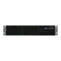
Intel S2600WF Series Configuration Manual (23 pages)
Data Center Blocks for Nutanix Enterprise Cloud
Brand:
Intel
| Category:
Server
| Size: 1.54 MB
Table of Contents
Table of Contents
5
1 Overview
6
Product Family Summary
6
Table 1. Overview of Intel® DCB for Nutanix* Enterprise Cloud Systems
6
2 System Configurations
7
System Based on Intel® Server Board S2600WF Family
7
Figure 1. System Based on Intel® Server Board S2600WF Family Feature Set Identification
8
Table 2. System Based on Intel® Server Board 2600WF Family
9
System Based on Intel® Compute Module HNS2600BPB Family
10
Figure 2. Intel® Server Chassis H2224XXLR3 Feature Set Identification
10
Figure 3. Intel® Compute Module HNS2600BPB24NU Feature Set Identification
11
Table 3. System Based on Intel® Compute Module HNS2600BP Family
12
Required Options
13
Processor Options
13
Memory Options
13
Table 4. Intel® DCB for Nutanix* Enterprise Cloud Processor Options
13
Storage Options
14
Networking Options
14
Table 5. Intel® Ethernet Adapters
14
3 Optional Configuration Accessories and Upgrades
16
Rail Options
16
Table 6. Rail Options
16
System Based on Intel® Server Board S2600WF Family Options
17
Table 7. System Based on Intel® Server Board S2600WF Family Options
17
4 Spare and Replacement Parts
20
Table 8. Unique Spare Parts for Intel® DCB for Nutanix* Enterprise Cloud Systems
20
5 Extended Warranties
21
Table 9. Extended Warranties
21
Appendix A. Additional Resources
22
A.1. System Based on Intel® Server Board S2600WF Family
22
A.2. System Based on Intel® Compute Module HNS2600BPB Family
22
Appendix B. Glossary
23
Advertisement
Related Products
Intel S2600CP Family
Intel S2600TP series
Intel S2600CW
Intel S7000FC4UR - Server System - 0 MB RAM
Intel SC5400RA - Server System - 0 MB RAM
Intel SR2612UR - Server System - 0 MB RAM
Intel SC5650
Intel SR2520SAFNA - Server System - 0 MB RAM
Intel SPSH4 - Server Platform - 0 MB RAM
Intel SC5650-DP
Intel Categories
Motherboard
Computer Hardware
Server
Server Board
Desktop
More Intel Manuals
Login
Sign In
OR
Sign in with Facebook
Sign in with Google
Upload manual
Upload from disk
Upload from URL