Sign In
Upload
Manuals
Brands
Graco Manuals
Paint Sprayer
295540
Graco 295540 Manuals
Manuals and User Guides for Graco 295540. We have
2
Graco 295540 manuals available for free PDF download: Instructions Manual, Operation, Parts, Service, Repair
Graco 295540 Instructions Manual (54 pages)
Brand:
Graco
| Category:
Paint Sprayer
| Size: 2.81 MB
Table of Contents
Table of Contents
2
Related Manuals
2
Models
3
Warnings
4
Important Isocyanate (ISO) Information
6
Isocyanate Conditions
6
Material Self-Ignition
7
Keep Components a and B Separate
7
Moisture Sensitivity of Isocyanates
7
Foam Resins with 245 Fa Blowing Agents
7
Changing Materials
7
Component Identification
8
Model GX-7A
8
Model GX-7 DI
9
Model GX-7 400
10
Centerline Components
11
Mixing Module
14
Operation
15
Grounding
15
Air Hose Connection
15
Safety Lock
15
Manual Valves
16
Coupling Block
16
Pressure Relief Procedure
17
Flush Gun
18
Initial Set up
18
Daily Start-Up
19
Daily Shutdown
20
Optional Configuration
21
Air Inlet Configuration
21
Install Mixing Module
21
Install PCD
22
Check Adjustment of Valving Rod
22
Adjust Valving Rod
23
Maintenance
24
Gun Service Kits
24
Clean Spray Gun
24
Repair
26
Service Screen Screw
26
Remove and Service Centerline Components
26
Install Centerline Components
28
Replace End Cap and Air Piston Assembly
29
Replace Trigger Valve O-Rings
30
Clean Mixing Module
31
Install Mixing Module
32
Clean Pattern Control Disc
32
Parts
34
GX-7A Assembly
34
DI Assembly (295541)
36
400 Assembly (295540)
38
GX-7A Handle (24K734)
40
DI Handle (295809)
42
400 Handle (24K733)
44
Coupling Block Assembly (295383)
46
Specifications
47
GX-7A MIX Module Kit
47
Set-Up Chart for GX-7A Model
48
GX-7 400 MIX Module Kit
49
Set-Up Chart for GX-7 400 Model
50
GX-7 DI Model Specifications
51
Tip Kits
52
Tool Kit
52
Technical Specifications
53
California Proposition 65
53
Graco Standard Warranty
54
Advertisement
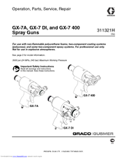
Graco 295540 Operation, Parts, Service, Repair (50 pages)
3500 psi (24 MPa, 240 bar) Maximum Working Pressure
Brand:
Graco
| Category:
Paint Sprayer
| Size: 3.46 MB
Table of Contents
Models
2
Table of Contents
2
Warnings
3
Overall View
6
Centerline Components
8
Mixing Module
10
Operation Basics
11
Isocyanate Hazard
11
Keep a and B Components Separate
11
Grounding
11
Safety Position
11
Air Hose Connection
12
Coupling Block
13
Air Inlet Configuration
14
Mixing Module and PCD Installation
15
Valving Rod Adjustment
16
Initial Set up
17
Daily Start-Up
18
Daily Shutdown
18
Pressure Relief Procedure
19
Maintenance
20
Gun Service Kits
20
Clean Spray Gun Procedure
20
Flush Gun
21
Repair
22
Service Screen Screw
22
Remove Centerline Components
22
Install Centerline Components
24
Replace End Cap and Air Piston Assembly
25
Replace Trigger Valve O-Rings
26
Clean Mixing Module
27
Install Mixing Module
28
Clean Pattern Control Disc
29
Parts
30
GX-7A Model Final Assembly
30
DI Model Final Assembly (295541)
32
400 Model Final Assembly (295540)
34
GX-7A Model Handle Assembly (295810)
36
DI Model Handle Assembly (295809)
38
400 Model Handle Assembly (295799)
40
Coupling Block Assembly (295383)
42
Part No. Description
42
Specifications
43
GX-7A MIX Module Kit
43
Set-Up Chart for GX-7A Model
44
GX-7 400 MIX Module Kit
45
Set-Up Chart for GX-7 400 Model
46
GX-7 DI Model Specifications
47
Tip Kits
48
Tool Kits
48
Technical Data
49
Graco Standard Warranty
50
Graco Information
50
Advertisement
Related Products
Graco 295530
Graco 295532
Graco 295531
Graco 295533
Graco 295541
Graco 295542
Graco 295543
Graco 295544
Graco 295545
Graco 295812
Graco Categories
Paint Sprayer
Water Pump
Stroller
Baby & Toddler Furniture
Industrial Equipment
More Graco Manuals
Login
Sign In
OR
Sign in with Facebook
Sign in with Google
Upload manual
Upload from disk
Upload from URL