Sign In
Upload
Manuals
Brands
GEM Manuals
Control Unit
428
GEM 428 Butterfly Valve Metal Manuals
Manuals and User Guides for GEM 428 Butterfly Valve Metal. We have
1
GEM 428 Butterfly Valve Metal manual available for free PDF download: Installation, Operating And Maintenance Instructions
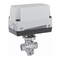
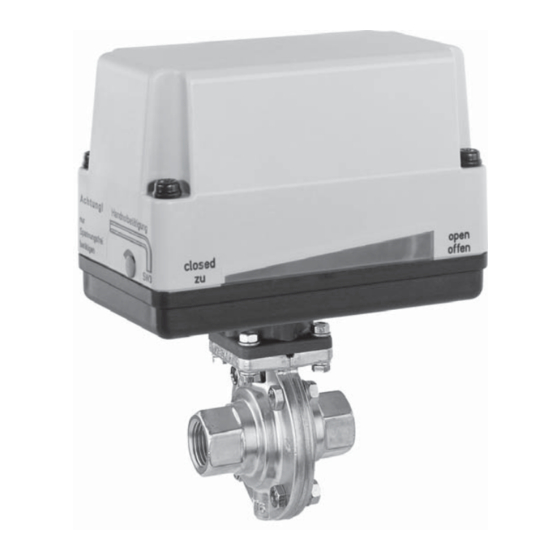
GEM 428 Installation, Operating And Maintenance Instructions (60 pages)
Butterfly Valve, Metal, DN 15 - 50
Brand:
GEM
| Category:
Control Unit
| Size: 2.06 MB
Table of Contents
Deutsch
2
Table of Contents
2
1 Allgemeine Hinweise
3
2 Allgemeine Sicherheitshinweise
3
Hinweise für Service
3
Warnhinweise
3
Verwendete Symbole
4
3 Begriffsbestimmungen
4
4 Vorgesehener Einsatzbereich
4
5 Auslieferungszustand
4
6 Technische Daten
5
7 Bestelldaten
7
8 Herstellerangaben
8
Transport
8
Lieferung und Leistung
8
Lagerung
8
Benötigtes Werkzeug
8
9 Funktionsbeschreibung
8
10 Geräteaufbau
8
11 Montage und Bedienung
9
Montage der Absperrklappe
9
12 Elektrischer Anschluss
11
Anschlusspläne 12
12
Auf-Zu-Steuerung (Code A0) - 12 V DC (Code B1) und 24 V DC (Code C1)
12
Auf-Zu-Steuerung (Code A0) - 12 V AC (Code B4) und 24 V AC (Code C4)
13
Auf-Zu-Steuerung (Code A0 mit K-Nr. 6410) - 12 V DC (Code B1)
14
Auf-Zu-Steuerung mit
14
Auf-Zu-Steuerung mit einem Steckverbinder (Code A0 mit K-Nr. 6598) - 12 V, 24 V AC und DC
17
Auf-Zu-Steuerung mit
18
Anschlusspläne 100-250
20
Auf-Zu-Steuerung (Code A0)
20
Auf-Zu-Steuerung mit
21
(Code AE mit K-Nr. 6722) - 100-250 V AC (Code O4)
22
13 Bedienung
23
Optische Stellungsanzeige
23
Handnotbetätigung (Optional)
23
Endschalter Einstellen
23
14 Montage / Demontage
24
Von Ersatzteilen
24
Demontage Absperrklappe
24
(Antrieb vom Körper Lösen)
24
Demontage Absperrdichtung
24
Montage Absperrdichtung
25
Montage Antrieb auf
25
15 Inbetriebnahme
26
16 Inspektion und Wartung
26
17 Demontage
27
18 Entsorgung
27
20 Hinweise
27
22 Schnittbild und Ersatzteile
29
23 Einbauerklärung
30
English
31
General Information
32
General Safety Information
32
Information for Service and Operating Personnel
32
Warning Notes
32
Symbols Used
33
Definition of Terms
33
Intended Area of Use
33
Condition as Supplied to
33
Technical Data
34
Order Data
36
Manufacturer's Information
37
Transport
37
Delivery and Performance
37
Storage
37
Tools Required
37
Functional Description
37
Construction
37
Installation and Operation
38
Installation of the Butterfly Valve
38
Electrical Connection
40
Connection Diagrams 12
41
Open/Close Control (Code A0) - 12 V DC (Code B1) and 24 V DC (Code C1)
41
Open/Close Control (Code A0) - 12 V AC (Code B4) and 24 V AC (Code C4)
42
Open/Close Control (Code A0 with K-No. 6410) - 12 V DC (Code B1) and 24 V DC (Code C1)
43
Open/Close Control with One Connector (Code A0 with K-No. 6598) - 12 V, 24 V AC and DC
46
Open/Close Control with
47
Open/Close Control with
48
Connection Diagrams 100-250 V
49
Open/Close Control (Code A0)
49
100-250 V AC (Code O4)
50
Open/Close Control with 31 2 Potential-Free Limit Switches
50
Manual Override (Option)
52
Operation
52
Optical Position Indicator
52
Setting the Limit Switches
52
Spare Parts
53
Butterfly Valve Disassembly
53
(Removing Actuator from Body)
53
Disassembling the Seat
53
Actuator Mounting on the Butterfly
54
Valve Body 5
54
Assembling the Seat
54
Assembly / Disassembly of
53
Commissioning
55
Inspection and Servicing
55
Disassembly
56
Disposal
56
Returns
56
Information
56
Troubleshooting / Fault
57
Sectional Drawing and Spare
58
Declaration of Incorporation
59
Advertisement
Advertisement
Related Products
GEM 4221
GEM 4222
GEM 423
GEM 41125D112140
GEM 415
GEM 410
GEM 566 20D88C1 4C1S0G2500 0A
GEM 566 15D88C1 4C1S0G1000 0A
GEM 4242
GEM 4200
GEM Categories
Control Unit
TV Mount
Measuring Instruments
Valve Positioners
Accessories
More GEM Manuals
Login
Sign In
OR
Sign in with Facebook
Sign in with Google
Upload manual
Upload from disk
Upload from URL