Sign In
Upload
Manuals
Brands
Fujitsu Manuals
Server
PRIMERGY RX300 S8
Fujitsu PRIMERGY RX300 S8 Manuals
Manuals and User Guides for Fujitsu PRIMERGY RX300 S8. We have
3
Fujitsu PRIMERGY RX300 S8 manuals available for free PDF download: Upgrade And Maintenance Manual, Instructions Manual, Datasheet
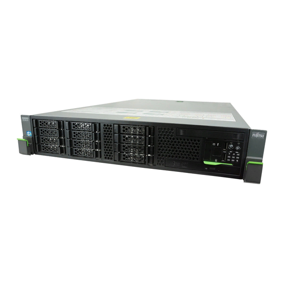
Fujitsu PRIMERGY RX300 S8 Upgrade And Maintenance Manual (502 pages)
Brand:
Fujitsu
| Category:
Server
| Size: 15.92 MB
Table of Contents
Copyright and Trademarks
2
Version History
6
Table of Contents
7
1 Introduction
25
Notational Conventions
26
2 Before You Start
27
Classification of Procedures
29
Customer Replaceable Units (CRU)
29
Upgrade and Repair Units (URU)
30
Field Replaceable Units (FRU)
31
Average Task Duration
31
Tools You Need at Hand
32
Documents You Need at Hand
36
3 Important Information
39
Safety Instructions
39
Energy Star
47
CE Conformity
47
FCC Class a Compliance Statement
48
Environmental Protection
49
4 Basic Hardware Procedures
51
Using Diagnostics Information
51
Locating the Defective Server
51
Determining the Error Class
52
Global Error Indicator
52
Customer Self Service (CSS) Indicator
52
Locating the Defective Component
53
Local Diagnostic Indicators on the Front
53
Local Diagnostic Indicators on the System Board
53
Shutting down the Server
54
Disconnecting Power Cords
54
Getting Access to the Component
57
Extending the Server out of the Rack
57
Removing the Server from the Rack
59
Opening the Server
60
Removing the Housing Cover
61
Removing the Air Duct
62
Reassembling
63
Installing the Air Duct
63
Closing the Server
64
Mounting the Housing Cover
65
Mounting the Server in the Rack
65
Seating the Server on the Rack Rails
65
Sliding the Server into the Rack
68
Connecting the Server to the Power Source
69
Switching on the Server
71
5 Basic Software Procedures
73
Starting the Maintenance Task
73
Disabling Bitlocker Functionality
73
Disabling SVOM Boot Watchdog Functionality
74
Viewing Boot Watchdog Settings
74
Configuring Boot Watchdog Settings
75
Removing Backup and Optical Disk Media
76
Verifying and Configuring the Backup Software Solution
77
Note on Server Maintenance in a Multipath I/O Environment
77
Switching on the ID Indicator
80
Completing the Maintenance Task
80
Updating or Recovering the System Board BIOS and Irmc
80
Updating or Recovering the System Board BIOS
81
Updating or Recovering the Irmc
81
Verifying System Information Backup / Restore
83
Updating RAID Controller Firmware
84
Enabling Option ROM Scan
85
Verifying and Configuring the Backup Software Solution
86
Resetting the Boot Retry Counter
87
Viewing the Boot Retry Counter
87
Enabling SVOM Boot Watchdog Functionality
89
Enabling Replaced Components in the System BIOS
89
Verifying the Memory Mode
90
Verifying the System Time Settings
91
Viewing and Clearing the System Event Log (SEL)
92
Viewing the SEL
92
Clearing the SEL
93
Updating the NIC Configuration File in a Linux Environment
93
Enabling Bitlocker Functionality
95
Performing a RAID Array Rebuild
96
Looking up Changed MAC / WWN Addresses
96
Looking up MAC Addresses
96
Looking up WWN Addresses
97
Using the Chassis ID Prom Tool
98
Configuring LAN Teaming
99
After Replacing / Upgrading LAN Controllers
99
After Replacing the System Board
99
Switching off the ID Indicator
100
Performing a Fan Test after Replacing a Defective Fan
100
6 Power Supply Units
103
Basic Information
103
Power Supply Unit Configurations
104
Assembly Rules
104
Installing Hot-Plug Power Supply Units
105
Preliminary Steps
105
Removing the Dummy Cover
105
Installing a Hot-Plug Power Supply Unit
106
Concluding Steps
107
Removing a Hot-Plug Power Supply Unit
107
Preliminary Steps
107
Removing a Hot-Plug Power Supply Unit
108
Installing a Dummy Cover
109
Concluding Steps
109
Replacing a Hot-Plug Power Supply Unit
110
Preliminary Steps
110
Removing the Defective Hot-Plug Power Supply Unit
110
Installing the New Hot-Plug Power Supply Unit
111
Concluding Steps
111
Upgrading a Power Supply from 450 W to 800 W
112
Preliminary Steps
112
Removing the Hot-Plug Power Supply Unit
112
Installing the New Hot-Plug Power Supply Unit
113
Concluding Steps
114
Replacing the Power Backplane
114
Preliminary Steps
114
Disconnecting Power Cables
115
Removing the Power Backplane
116
Installing the Power Backplane
118
Reconnecting Power Cables
120
Concluding Steps
120
7 Hard Disk Drives / Solid State Drives
121
Basic Procedures
122
Inch Hard Disk Drives
122
6X3.5-Inch HDD Configuration
122
Mounting Order
122
HDD Naming Scheme
123
4X3.5-Inch HDD Configuration with Tape/Rdx Drive
123
Mounting Order with Tape/Rdx Drive
123
HDD Naming Scheme with Tape Drive
124
Installing 3.5-Inch HDD Modules
124
Preliminary Steps
124
Removing a 3.5-Inch Dummy Module
125
Installing a 3.5-Inch HDD Module
126
Concluding Steps
127
Removing 3.5-Inch HDD Modules
127
Preliminary Steps
127
Removing a 3.5-Inch HDD Module
128
Installing a 3.5-Inch Dummy Module
129
Concluding Steps
129
Replacing a 3.5-Inch HDD Module
130
Preliminary Steps
130
Removing a 3.5-Inch HDD Module
130
Installing a 3.5-Inch HDD Module
131
Concluding Steps
131
Inch HDD / SSD Configurations
131
Mounting Order for 2.5-Inch Hdds / Ssds
131
HDD / SSD Mounting Order for 4X 2.5-Inch HDD / SSD Configuration
131
HDD / SSD Naming Scheme for 4X 2.5-Inch HDD / SSD Configuration
131
HDD / SSD Mounting Order for 8X 2.5-Inch HDD / SSD Configurations
132
HDD / SSD Naming Scheme for 8X 2.5-Inch HDD / SSD Configurations
133
HDD / SSD Mounting Order for 12X 2.5-Inch HDD / SSD Configuration
133
HDD / SSD Naming Scheme for 12X 2.5-Inch HDD / SSD Configuration
134
HDD / SSD Mounting Order for 12X 2.5-Inch HDD / SSD Configuration
134
HDD / SSD Naming Scheme 12X 2.5-Inch HDD / SSD Configuration
135
Installing 2.5-Inch HDD / SSD Modules
135
Preliminary Steps
136
Removing a 2.5-Inch Dummy Module
136
Installing a 2.5-Inch HDD / SSD Module
137
Concluding Steps
138
Removing 2.5-Inch HDD / SSD Modules
138
Preliminary Steps
138
Removing a 2.5-Inch HDD / SSD Module
139
Installing a 2.5-Inch Dummy Module
140
Concluding Steps
141
Replacing a 2.5-Inch HDD / SSD Module
141
Preliminary Steps
142
Removing a 2.5-Inch HDD / SSD Module
142
Installing a 2.5-Inch HDD / SSD Module
142
Concluding Steps
142
Replacing SAS / SATA HDD / SSD Backplanes
143
Replacing the 3.5-Inch HDD SAS / SATA Backplane
143
Preliminary Steps
143
Removing the 3.5-Inch HDD SAS / SATA Backplane
144
Installing the 3.5-Inch HDD SAS / SATA Backplane
146
Concluding Steps
148
Replacing the 4X 2.5-Inch HDD SAS Backplane
148
Preliminary Steps
148
Removing the HDD Cage
149
Removing the 4X 2.5-Inch SAS HDD Backplane
150
Installing the 4X 2.5-Inch HDD SAS Backplane
151
Installing the HDD Cage
152
Concluding Steps
153
Replacing the 12X 2.5-Inch HDD SAS Backplane
153
Preliminary Steps
153
Removing the 12X2.5-Inch HDD SAS Backplane
154
Installing the 12X 2.5-Inch HDD SAS Backplane
155
Concluding Steps
157
8 System Fan
159
Basic Information
159
Replacing the System Fan
160
Preliminary Steps
160
Removing a System Fan
160
Installing a System Fan
161
Concluding Steps
161
Removing the Fan Box
162
Preliminary Steps
162
Installing the Fan Box
164
Concluding Steps
165
9 Expansion Cards and Backup Units
167
Basic Information
167
Expansion Cards and Backup Units
168
Handling Slot Brackets
172
Installing a Slot Bracket
172
Installing a Standard Slot Bracket
172
Installing a Slot Bracket to the Network Adapter D2735
174
Installing a Slot Bracket to the Network Adapter D2745
176
Installing a Slot Bracket to the Network Adapter D2755
178
Installing a Slot Bracket to the USB 3.0 Interface Card D3305
180
Removing a Slot Bracket
181
Expansion Cards
182
Installing Expansion Cards
182
Preliminary Steps
182
Removing the Slot Bracket
182
Installing an Expansion Card
183
Concluding Steps
184
Removing Expansion Cards
185
Preliminary Steps
185
Removing an Expansion Card
185
Installing a PCI Slot Bracket
187
Concluding Steps
187
Replacing Expansion Cards
188
Preliminary Steps
188
Removing an Expansion Card
188
Installing an Expansion Card
189
Connecting Cables to the Expansion Card
189
Connecting a Battery Backup Unit to the Expansion Card
189
Concluding Steps
189
SAS RAID Controller in PCI Slot 7
190
Installing the SAS RAID Controller
190
Preliminary Steps
190
Preparing the SAS RAID Controller
190
Installing the SAS RAID Controller
191
Connecting Cables to the Expansion Card
192
Connecting a Backup Unit to the Expansion Card
192
Concluding Steps
192
Removing the SAS RAID Controller
193
Preliminary Steps
193
Removing the SAS RAID Controller
194
Concluding Steps
194
Replacing the SAS RAID Controller
195
Preliminary Steps
195
Removing the Defective SAS RAID Controller
196
Installing the New SAS RAID Controller
196
Connecting Cables to the Expansion Card
196
Connecting a Backup Unit to the Expansion Card
196
Concluding Steps
196
Modular LAN Controller in PCI Slot 1
197
Basic Information
197
Installing the Modular LAN Controller
197
Preliminary Steps
197
Connecting the NCSI Sideband Cable to the Modular LAN Controller
198
Installing the Modular LAN Controller
200
Connecting the NCSI Sideband Cable to the System Board
201
Concluding Steps
202
Concluding Software Tasks
203
Removing the Modular LAN Controller
204
Preliminary Steps
204
Concluding Steps
205
Replacing the Modular LAN Controller
206
Preliminary Steps
206
Removing the Modular LAN Controller
206
Installing the Modular LAN Controller
207
Concluding Steps
207
Backup Units
208
Basic Information
208
Installing a BBU
209
Preliminary Steps
209
Connecting the BBU Cable to the BBU
210
Installing the BBU in the Holder
211
Installing the BBU Holder Onto the Air Duct
211
Installing the Air Duct with a BBU
213
Concluding Steps
214
Removing a BBU
215
Preliminary Steps
215
Removing the Air Duct with a BBU
216
Removing the BBU Holder from the Air Duct
217
Concluding Steps
217
Replacing a BBU
218
Preliminary Steps
218
Removing a BBU from the Air Duct
218
Removing the BBU from the BBU Holder
219
Installing a New BBU
220
Concluding Steps
220
Installing a FBU
221
Preliminary Steps
221
Installing TFM to the RAID Controller (if Applicable)
221
Preparing the FBU
223
Connecting the FBU Cable to the FBU
225
Installing the FBU Holder Onto the Air Duct
225
Installing the Air Duct with an FBU
226
Concluding Steps
228
Removing a FBU
228
Preliminary Steps
228
Removing the Air Duct with an FBU
229
Removing the FBU Holder from the Air Duct
230
Concluding Steps
230
Replacing a FBU
231
Preliminary Steps
231
Removing a FBU from the Air Duct
232
Disconnecting the FBU Cable from the FBU
232
Removing the FBU from the Holder
233
Installing a New FBU
233
Concluding Steps
233
Handling SFP+ Transceiver Modules
234
Installing SFP+ Transceiver Modules
234
Removing an SFP+ Transceiver Module
238
Replacing SFP+ Transceiver Modules
240
10 Main Memory
243
Basic Information
244
Memory Sequence
245
Population Rules
245
Independant Channel Mode
247
Mirrored Channel and Performance Modes
248
Rank Sparing Mode
249
Installing Memory Modules
253
Preliminary Steps
253
Installing a Memory Module
253
Concluding Steps
255
Removing Memory Modules
256
Preliminary Steps
256
Removing a Memory Module
256
Concluding Steps
258
Replacing Memory Modules
258
Preliminary Steps
258
Removing the Defective Memory Module
259
Installing a New Memory Module
259
Concluding Steps
259
11 Processors
261
Basic Information
262
Supported Processors
262
Processor Locations
262
Installing Processors
263
Preliminary Steps
263
Installing the Processor
263
Opening the Load Plate
264
Installing the New Processor
268
Removing the Protective Socket Cover
269
Closing the Load Plate
271
Concluding Steps
272
Removing Processors
273
Preliminary Steps
273
Removing a Processor
273
Opening the Load Plate
274
Removing the Processor
278
Closing the Load Plate
279
Installing the Protective Cover
280
Closing the Load Plate
282
Concluding Steps
283
Upgrading or Replacing Processors
284
Preliminary Steps
284
Upgrading or Replacing a Processor
284
Concluding Steps
285
Handling Processor Heat Sinks
286
Preliminary Steps
286
Installing Processor Heat Sinks
286
Preparing the Heat Sink and Processor
288
Installing the Heat Sink
289
Removing Processor Heat Sinks
291
Replacing Processor Heat Sinks
293
Removing the Processor Heat Sink
293
Applying Thermal Paste
293
Installing the Processor Heat Sink
293
Concluding Steps
293
Applying Thermal Paste
294
12 Accessible Drives
297
Basic Informations
298
Installing a Local Service Display (LSD) Module
299
Preliminary Steps
299
Removing the LSD Dummy Cover
300
Installing a LSD Module
301
Concluding Steps
302
Removing a LSD Module
303
Preliminary Steps
303
Removing the LSD Module
303
Concluding Steps
305
Replacing a LSD Module
305
Preliminary Steps
306
Removing the Defective LSD Module
306
Installing the New LSD Module
306
Concluding Steps
306
Installing the Optical Disk Drive (ODD)
306
Preliminary Steps
307
Removing the ODD Dummy Module
307
Preparing an ODD
308
Installing an ODD
310
Concluding Steps
310
Removing the Optical Disc Drive (ODD)
311
Preliminary Steps
311
Removing the ODD
312
Concluding Steps
315
Replacing an ODD
315
Preliminary Steps
316
Removing the Defective ODD
316
Installing the New ODD
316
Concluding Steps
316
Installing a Tape/Rdx Drive in 3.5-Inch Version
317
Preliminary Steps
317
Installing a Tape/Rdx Drive in the Cage
317
Installing the Tape/Rdx Drive
319
Connecting the Tape/Rdx Drive
321
Connecting the Tape/Rdx Drive to the Systemboard
321
Connecting the RDX Drive to the USB 3.0 Interface Card
321
Concluding Steps
323
Removing a Tape/Rdx Drive in 3.5-Inch Version
323
Preliminary Steps
324
Removing the Drive Cage
324
Removing a Tape/Rdx Drive out of the Cage
325
Concluding Steps
326
Replacing the Tape/Rdx Drive in 3.5-Inch Version
327
Preliminary Steps
327
Removing the Defective Tape/Rdx Drive
327
Installing the New Tape/Rdx Drive
327
Concluding Steps
328
Installing a Tape/Rdx Drive in 2.5-Inch Version
328
Preliminary Steps
328
Installing a Tape/Rdx Drive in the Cage
329
Installing the Tape/Rdx Drive
331
Connecting the Tape/Rdx Drive
331
Connecting the Tape/Rdx Drive to the System Board
331
Connecting the RDX Drive to the USB 3.0 Interface Card
332
Concluding Steps
335
Removing a Tape/Rdx Drive in 2.5-Inch Version
335
Preliminary Steps
335
Removing the Drive Cage
336
Removing a Tape/Rdx Drive out of the Cage
337
Concluding Steps
339
Replacing the Tape/Rdx Drive in 2.5-Inch Version
339
Preliminary Steps
339
Removing the Defective Tape/Rdx Drive
340
Installing the New Tape/Rdx Drive
340
Concluding Steps
340
Installing an LTO Drive in 2.5-Inch Version
340
Preliminary Steps
341
Removing the Drive Cage
341
Removing the Tape Drive Dummy Module
343
Installing an LTO Drive in the Cage
344
Installing the LTO Cage
347
Concluding Steps
349
Removing an LTO Drive in 2.5-Inch Version
350
Preliminary Steps
350
Removing the Drive Cage
351
Removing an LTO Drive out of the Cage
354
Installing the Tape Drive Dummy Module
356
Concluding Steps
358
Replacing the LTO Drive in 2.5-Inch Version
359
Preliminary Steps
359
Removing the Defective LTO Drive
359
Installing the New LTO Drive
359
Concluding Steps
360
13 Front Panel and External Connectors
361
Front Panel Module
361
Replacing the Front Panel Module
361
Preliminary Steps
362
Removing the Front Panel Module
363
Installing the Front Panel Module
365
Concluding Steps
368
Front VGA Connector
369
Installing the Front VGA Connector
369
Preliminary Steps
369
Removing the Front Panel Module
369
Preparing the Front Panel Module
370
Installing the Front VGA Connector
370
Re-Installing the Front Panel Module
371
Concluding Steps
372
Removing the Front VGA Connector
373
Preliminary Steps
373
Removing the Front VGA Cable
373
Removing the Front VGA Connector
374
Re-Installing the Front Panel Module
374
Concluding Steps
374
Replacing the Front VGA Connector
375
Preliminary Steps
375
Removing the Front Panel Module
375
Removing the Front VGA Connector
375
Installing the New Front VGA Connector
375
Re-Installing the Front Panel Module
376
Concluding Steps
376
Front LAN Connector
376
Installing the Front LAN Connector
376
Preliminary Steps
376
Removing the Front Panel Module
377
Preparing the Front Panel Module
377
Installing the Front LAN Connector
378
Installing the LAN Board
382
Concluding Steps
384
Using the Front Management LAN Connector
385
Removing the Front LAN Connector
386
Preliminary Steps
386
Removing the Front LAN Board
386
Removing the Front LAN Connector
388
Concluding Steps
391
Replacing the Front LAN Connector and Board
392
Preliminary Steps
392
Removing the Front Panel Module
392
Removing the Defective Front LAN Connector
392
Installing the New Front LAN Connector
392
Re-Installing the Front Panel Module
392
Concluding Steps
392
Front Cage
393
Replacing the Front Panel Cage
393
Preliminary Steps
393
Removing the Front Panel Cage
393
Re-Installing the Front Panel Cage
395
Concluding Steps
397
14 System Board and Components
399
Basic Information
399
Replacing the CMOS Battery
400
Preliminary Steps
400
Removing the Battery
401
Installing the CMOS Battery
402
Concluding Steps
402
USB Flash Module (UFM)
403
Installing the UFM
403
Preliminary Steps
403
Installing the UFM
404
Concluding Steps
405
Software Configuration
405
Removing the UFM
406
Preliminary Steps
407
Removing the UFM
407
Concluding Steps
408
Replacing the UFM
409
Preliminary Steps
409
Removing the UFM
409
Installing the New UFM
410
Concluding Steps
412
Software Configuration
412
Trusted Platform Module (TPM)
413
Installing the TPM
413
Preliminary Steps
413
Installing the TPM
414
Concluding Steps
417
Removing the TPM
418
Preliminary Steps
419
Removing the TPM
421
Concluding Steps
423
Replacing the TPM
423
Preliminary Steps
423
Removing the TPM
424
Re-Installing the TPM
424
Concluding Steps
425
Onboard SAS Enabling Key
425
Installing the Onboard SAS Enabling Key
425
Preliminary Steps
425
Installing the Onboard SAS Enabling Key
426
Concluding Steps
428
Removing the Onboard SAS Enabling Key
428
Preliminary Steps
428
Removing Onboard SAS Enabling Key
429
Concluding Steps
429
Replacing the Onboard SAS Enabling Key
430
Preliminary Steps
430
Concluding Steps
430
Replacing the System Board
431
Preliminary Steps
433
Removing the Defective System Board
434
Installing the System Board
436
Mounting the System Board
436
Swapping Processors
438
Concluding Steps
439
15 Conversion Configurations
441
Basic Information
441
Supported Conversions
441
SAS Cabling
442
Basic Procedures
442
Preliminary Steps
443
Removing the
443
Removing HDD Cages and Front Panel Cage
444
Installing HDD Cage and Front Panel Cage
445
Installing the
446
Multicage in Bay 4/5
446
Panelhousing in Bay 5
447
Converting
448
Configuration 2 to Configuration 4
448
Configuration 2 to Configuration 7
451
Configuration 2 to Configuration 3
455
Configuration 3 to Configuration 6
458
Configuration 4 to Configuration 7
461
Configuration 4 to Configuration 8
463
Configuration 7 to Configuration 8
464
Concluding Steps
464
16 Cables
465
List of Used Cables
465
Cabling Plans
468
Configuration 1
468
Configuration 2
470
Configuration 3
472
Configuration 4
474
Configuration 5
475
Configuration 6
477
Configuration 7
479
Configuration 8
480
Modular LAN NCSI Sideband Cabling
481
17 Appendix
483
Mechanical Overview
483
Server Front
483
Server Rear
484
Server Interior
485
Configuration Tables
486
Hard Disk Drives / Solid State Drives Mounting Order
486
Memory Board Configuration Table
486
Expansion Card Configuration Table
486
Connectors and Indicators
487
Connectors and Indicators on the System Board
487
Onboard Connectors
487
Onboard Indicators and Controls
489
Connectors and Indicators on the I/O Panel
491
I/O Panel Connectors
491
I/O Panel Indicators
492
Connectors and Indicators on the Front Panel
494
Front Panel Connectors
494
Front Panel Controls and Indicators
495
Onboard Settings
499
Minimum Startup Configuration
500
Advertisement
Fujitsu PRIMERGY RX300 S8 Instructions Manual (31 pages)
System configurator and order information guide
Brand:
Fujitsu
| Category:
Server
| Size: 0.94 MB
Table of Contents
Table of Contents
1
Accessible Drives
3
Communication/Network
3
Hard Disk Drives
3
Memory
3
Processor
3
Miscellaneous
28
System Management Products (Remoteview)
28
Country Specific Power Cord
29
Change Report
31
Fujitsu PRIMERGY RX300 S8 Datasheet (12 pages)
Dual socket 2U rack server
Brand:
Fujitsu
| Category:
Server
| Size: 0.14 MB
Table of Contents
Rack Server
1
Features and Benefits
2
Technical Details
3
Main Board
3
Operating Environment
7
Communication, Network
10
Warranty
10
More Information
11
Advertisement
Advertisement
Related Products
Fujitsu PRIMERGY RX300 S7
Fujitsu PRIMERGY RX350 S7
Fujitsu PRIMERGY RX300 S6
Fujitsu PRIMERGY RX330 S1
Fujitsu PRIMERGY RX300 S5
Fujitsu Primergy RX300 S2
Fujitsu Primergy RX300 S4
Fujitsu Primergy RX300 S3
Fujitsu PRIMERGY RX350 S8
Fujitsu PRIMERGY RX600 S6
Fujitsu Categories
Air Conditioner
Laptop
Server
Scanner
Storage
More Fujitsu Manuals
Login
Sign In
OR
Sign in with Facebook
Sign in with Google
Upload manual
Upload from disk
Upload from URL