Sign In
Upload
Manuals
Brands
Fluke Manuals
Multimeter
8840A
Fluke 8840A Manuals
Manuals and User Guides for Fluke 8840A. We have
2
Fluke 8840A manuals available for free PDF download: Instruction Manual
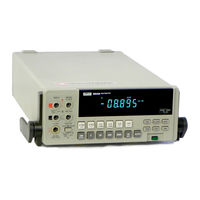
Fluke 8840A Instruction Manual (181 pages)
Brand:
Fluke
| Category:
Multimeter
| Size: 26.39 MB
Table of Contents
Multimeter Safety
3
Section Guide
5
Table of Contents
7
List of Tables
13
List of Illustrations
14
Introduction and Specifications
17
Options and Accessories
17
Operating Instructions
25
Installation
25
Installing the Power-Line Fuse
25
Connecting to Line Power
25
Operating Features
26
Power-Up Features
26
Front and Rear Panel Features
26
Line Voltage Selection Setting
26
Display Features
27
Error Messages
27
Overrange Indication
27
Rack-Mount Kits
27
Front Panel Features
28
Rear Panel Features
30
Diagnostic Self-Tests
31
Ranging
31
Triggering
31
Autorange
31
Error Codes
32
Making Measurements
33
Reading Rates and Noise Rejection
33
Automatic Setting Time Delay
33
External Trigger Input
33
Measuring Voltage and Resistance
34
Measuring Current
34
Current Fuse Protection
34
Offset Measurements
34
External Cleaning
35
Remote Programming
37
Capabilities
37
Bus Set-Up Procedure
37
An Overview of Remote Operation
37
A Note about Examples
38
Device-Dependent Command Set
38
Bn (Offset Commands)
38
IEEE-488 Address Selection
38
Remote Operation Block Diagram
39
Cn (Calibration Commands)
40
Dn (Display Commands)
40
Fn (Function Commands)
40
Get Commands
40
Commands Which Correspond to the Front Panel
41
G0 (Get Instrument Configuration)
43
G1 (Get SRQ Mask)
43
G2 (Get Calibration Prompt)
43
Output Data Format
44
G3 (Get User-Defined Message)
45
G4 (Get Calibration Status)
45
G5 (Get IAB Status)
45
G6 (Get YW Status)
45
N (Numeric Entry Command)
46
Put Commands
46
P0 (Put Instrument Configuration)
46
P1 (Put SRQ Mask)
46
Status Data
47
P3 (Put User-Defined Message)
48
Rn (Range Commands)
48
Sn (Reading Rate Commands)
48
Tn (Trigger Mode Commands)
48
Trigger Selection Logic Diagram
49
Z0 (Self-Test Command)
50
? (Single-Trigger Command)
50
Input Syntax
50
Definitions
50
Syntax Rules
51
Device-Dependent Messages
52
Output Data
53
Loading Output Data
53
Types of Output Data
53
Numeric Data and Error Messages
53
Output Priority
54
Service Requests
54
The Serial Poll Register
54
Talk-Only Mode
55
Address Messages
55
Universal Commands
55
Addressed Commands
55
Timing Considerations
56
Immediate Mode Commands
56
Example Programs
56
Immediate-Mode Commands for Various Controllers
56
Using the IBM PC
61
ASCI/IEEE Std 488-1978 Bus Codes
73
Measurement Tutorial
74
DC Voltage Measurement
74
Circuit Loading Error
74
Input Bias Current Error
74
Resistance Measurement
75
2-Wire Ohms
75
Correcting for Test Lead Resistance in 2-Wire Ohms
75
Circuit Loading Error Calculation
75
4-Wire Ohm
76
Applications of the Ohms Functions
76
Measuring Input Bias Current Error
76
Testing Diodes
77
Testing Electrolytic Capacitors
77
A Precision Current Source
78
DC Current Measurement
79
Reducing Thermal Voltages
79
AC Voltage and Current
79
True RMS Measurement
79
AC-Coupled AC Measurements
80
Burden Voltage Error Calculation
80
Waveform Comparison Chart
81
Combined AC and DC Measurements
82
Bandwidth
82
Zero-Input VAC Error
82
Reduction of Zero-Input Error
83
Theory of Operation
84
Overall Functional Description
84
Detailed Circuit Description
84
DC Scaling
84
Overall Functional Block Diagram
85
DC Scaling (VDC and Ma DC)
86
VDC Protection
87
Ma DC Scaling
87
Analog Filter
87
Track/Hold Circuit
87
OHMS Current Source
88
OHMS Protection
88
Track/Hold Amplifier
88
Track/Hold Circuit Configurations
89
Timing Diagram for One A/D Cycle
90
OHMS Functions
91
4-Wire Ohms
91
Precision Voltage Reference
91
A/D Converter
92
Ohms Scaling
93
Timing/Data Control
94
Analog-To-Digital Converter
94
First Remainder-Store Period
95
Precision DAC
95
A/D Amplifier
95
Bootstrap Supplies
95
Keyboard
96
Digital Controller
96
In-Guard Microcomputer
96
Autozero Period
96
Digital Controller Block Diagram
97
Function and Range Control
98
A/D Control and Computation
98
Calibration Correction
98
Keyboard/Display Control
98
Read/Write Timing Diagrams for Internal Bus
99
Power Supply
100
Sample Rates and Reading Rates
100
Guard Crossing Circuit
100
Out-Guard Microcomputer
101
Guard Crossing
101
Bus Interface Circuitry
101
Signal Conditioning
101
Ieee-488 Interface Power Supply
102
TRUE RMS AC (Option -09)
102
VAC Scaling
102
Ma AC Scaling
102
True RMS AC-To-DC Converter
103
Maintenance
106
Performance Test
106
DC Voltage Test
106
Recommended Test Equipment
107
AC Voltage Test
108
Connections for Kelvin-Varley Voltage Divider
108
Resistance Test
109
Low- and MID-Frequency AC Voltage Test
109
High-Frequency AC Voltage Test
110
Calibration
111
Basic Calibration Procedure
111
Calibration Functions
113
A/D Calibration
113
A/D Calibration Test
113
Offset and Gain Calibration
114
Advanced Features and Special Considerations
115
Storing Variable Inputs
115
Calibrating Individual Ranges
115
Verifying Calibration
116
Prompts When Calibrating Individual Ranges
116
Tolerance Check
117
AC Calibration at Other Frequencies
117
Optimizing Use of the 5450A
117
Remote Calibration
118
Commands Used During Remote Calibration
118
Error Numbers Which Are Displayed When Commands Are Not Valid
120
Remote Erasure
120
Disassembly Procedure
121
Example Calibration Program
121
Example A/D Calibration Program
121
Case Removal
122
True RMS AC PCA Removal
122
IEEE-488 Interface PCA Removal
122
Main PCA Removal
122
8840A Disassembly
123
Front Panel Disassembly
127
Reassembly Procedure
127
Internal Fuse Replacement
129
Removing the Display Window
129
External Trigger Polarity Selection
130
Troubleshooting
130
Overall State Table
131
Circuitry Tested by the Analog Self-Tests
133
Self-Test Descriptions
134
Digital Controller Troubleshooting
136
In-Guard Microcomputer System
136
U202 Pin Diagram
137
Waveforms for In-Guard Troubleshooting Mode
138
Display System
139
Analog Control Signals
140
Waveforms for Display Logic
140
Evaluating Static Signals
141
Evaluating Dynamic Signals
141
Keyboard Wiring
141
Analog Control Devices
141
Analog Control Logic States
142
DC Scaling Troubleshooting
143
Track/Hold Troubleshooting
143
Typical Dynamic Control Signals
143
DC Scaling and Track/Hold Supply Voltages
143
Ohms Current Source Troubleshooting
144
Precision Voltage Reference Troubleshooting
144
Typical Output Waveforms for Track/Hold Circuit (TP103)
145
A/D Converter Troubleshooting
146
Output of A/D Amplifier (TP101)
146
Power Supply Troubleshooting
147
Waveforms at U101-24 and U101-25
147
Typical Bus Data Line Waveform
148
Waveforms at TP102 for Several Inputs on 2V DV Range
148
IEEE-488 Interface Troubleshooting
149
Calculating the A/D Reading from TP102 Waveform
149
Power Supply Voltages
149
Diagnostic Program
150
True RMS AC Troubleshooting
151
I/O Port Configurations
151
Isolating a Defective AC Stage
152
Internal Cleaning
153
Guard Crossing Troubleshooting
153
Cleaning Printed Circuit Assemblies
153
AC Signal Tracing
153
Cleaning after Soldering
154
Guard Crossing Test Waveforms
154
List of Replaceable Parts
156
How to Obtain Parts
157
Manual Status Information
157
Newer Instruments
157
Service Centers
157
8840A Digital Multimeter
158
A1 Main PCA
163
Main PCA, DC Scaling and F/R Switch
165
Display PCA
175
Advertisement
Fluke 8840A Instruction Manual (182 pages)
Brand:
Fluke
| Category:
Multimeter
| Size: 13.63 MB
Table of Contents
Section 1
8
Introduction and Specifications
6
Options and Accessories
6
Table of Contents
8
Introduction
10
Section 2
15
Operating Instructions
18
Introduction
18
Specifications
18
The 8840A Digital Multimeter
18
External Dimensions
25
Installing the Power-Line Fuse
26
Connecting to Line Power
26
Adjusting the Handle
26
Rack Mounting Kits
26
Operating Features
27
Front and Rear Panel Features
27
Power-Up Features
27
Line Voltage Selection Settings
27
Adjusting the Handle
27
Display Features
28
Error Messages
28
Overrange Indication
28
Rack-Mount Kits
28
Autorange
32
Continuous Trigger Mode
32
Diagnostic Self-Tests
32
External Trigger Mode
32
Manual Range
32
Ranging
32
Triggering
32
Automatic Settling Time Delay
34
External Trigger Input (Option -05 Only)
34
Reading Rates and Noise Rejection
34
Sample Complete Output (Option -05 Only)
34
Making Measurements
34
Input Overload Protection Limits
34
Overrange Indication
34
Measuring Voltage and Resistance
36
External Cleaning
36
Measuring Current
36
Remote Programming
38
Introduci'ion
38
Capabilities
38
Bus Set-Up Procedure
38
An Overview of Remote Operation
39
A Note about Examples
39
Device-Dependent Command Set
39
Bn (Offset Gommands)
39
IEEE-488 Address Seiection
39
Cn (Calibration Commands)
41
Fn (Function Commands)
41
Get Commands
43
G O (Get Instrument Configuration)
44
G1 (Get SRQ Mask)
44
G2 (Get Calibration Prompt)
44
Output Data Format
45
G3 (Get User-Defined Message)
46
G4 (Get Calibration Status)
46
G5 (Get IAB Status)
46
G6 (Get YW Status)
46
G7 (Get Error Status)
46
N (Numeric Entry Command)
47
Put Commands
47
P O (Put Instrument Configuration)
47
P2 (Put Calibration Value)
47
Sn (Reading Rate Commands)
49
Tn (Trigger Mode Commands)
49
Wn (Terminator Commands)
49
Trigger Selection Logic Diagram
50
ZO (Self-Test Command)
51
(Single-Trigger Command)
51
Input Syntax
51
Definitions
51
Input Processing
51
Syntax Rules
52
Interpretation of Messages
53
Output Data
54
Error Messages
54
Loading Output Data
54
Measurement Data
54
Numeric Data and Error Messages
54
Overrange Indication
54
Types of Output Data
54
Output Priority
55
Status Data
55
Service Requests
55
The Serial Poll Register
55
The SRQ Mask
55
Serial Poll Register
55
Interface Messages
56
Address Messages
56
Addressed Commands
56
Universal Commands
56
Talk-Only Mode
56
Timing Considerations
57
Example Program: Taking 10 Readings
58
Example Program: Taking Readings with Local Control
59
Example Programs: Using the IBM PC
62
Example Programs
72
DC Voltage Measurement
75
Circuit Loading Error
75
Input Bias Current Error
75
Introduction
75
Measurement Tutorial
75
Resistance Measurement
76
2-Wire Ohms
76
Circuit Loading Error Calculation
76
4-Wire Ohms
77
Applications of the Ohms Functions
77
Measuring Input Bias Current Error
77
Testing Diodes
78
Testing Electrolytic Capacitors
78
2-Wire Ohms Measurement
78
Aprecision Current Source
79
4-Wire Ohms Measurement
79
Ac Voltage and Current Measurement
80
DC Current Measurement
80
Reducing Thermal Voltages
80
AC-Coupled AC Measurements
81
Burden Voltage Error Calculation
81
Crest Factor
81
Waveform Comparison Chart
82
Bandwidth
83
Typical Crest Factors for Various Waveforms
83
Combined AC and DC Measurement
83
Combined AC and DC Measurements
83
Zero-Input VAC Error
83
Detailed Circuit Description
85
DC Scaling
85
VDC Scaling
85
Introduction
85
Overall Functional Description
85
Theory of Operation
85
DC Scaling (VDC and Rna DC)
87
VDC Protection
88
DC Scaling
88
Hold Configuration
88
Analog Filter
88
Pre-Charge Configuration
88
Precision Voltage Reference
88
Settling Configuration
88
Tracwhold Circuit
88
Ohms Current Source
89
Ohms Protection
89
2-Wire Ohms
92
Ohms Functions
92
Ohms Scaling
94
Display
96
Precision DAC
96
Keyboard
97
Function and Range Control
99
Calibration Correction
99
Troubleshooting Modes
99
Guard-Crossing Communication
99
Guard Crossing
100
Power Supply
101
Ieee-488 Interface (Option -05)
102
Out-Guard Microcomputer
102
Signal Conditioning
102
Frequency Response Trimming
103
IEEE488 Interface Power Supply
103
Ma AC Scaling
103
True Rms Ac (Option -09)
103
True RMS AC-To-DC Conversion
103
VAC Scaling
103
Maintenance
107
Introduction
107
Performance Test
107
Diagnostic Self-Tests
107
DC Voltage Test
107
AC Voltage Test (Option -09 Only)
109
Resistance Test
110
DC Current Test
111
AC Current Test (Option -09 Only)
112
Calibration
113
Initial Procedure
113
Offset and Gain Calibration
113
High-Frequency Ac Calibration
115
Advanced Features and Special Considerations
116
Storing Variable Inputs
116
Erasing Calibration Memory
117
Verifying Cajjbration
117
Ac Calibration at Other Frequencies
118
Optimizing Use of the 5450A
118
Tolerance Check
118
Remote Calibration
119
Remote Erasure
121
Example Calibration Program
122
Disassembly Procedure
122
Case Removal
123
True RMS AC PCA Removal (Option -09)
123
IEEE-488 Interface PCA Removal (Option -05 Only)
123
Main PCA Removal
123
Front Panel Disassembly
128
Reassembly Procedure
128
Internal Fuse Replacement
130
External Trigger Polarity Seleci1On
131
EXTERNAL TRIGGER POLARITY SELECTION (Option -05 Only)
131
Initial Troubleshooting Procedure
131
Troubleshooting
131
Diagnostic Self-Tests
135
Self-Test Descriptions
135
Digital Controller Troubleshooting
137
In-Guard Microcomputer System
137
In-Guard Microcomputer
138
Address Latch (U219)
139
External Program Memory (XU222)
139
Calibration Memory (U220)
139
Relay Buffer (U201)
139
3-To-8 Chip Select Decoder (U208)
140
8-Bit Digit Driver (U215)
140
3-To-8 Strobe Decoder (U213)
140
8-Bit Digit Driver (U218)
140
8-Bit Segment Driver (U217)
140
Display Control (U212)
140
Display System
140
Hex Inverter (U203)
140
Hex Inverter (U221)
140
Analog Control Signals
141
Keyboard Wiring
141
Quad or Gate ( ' 2 1 1)
141
Evaluating Dynamic Signals
142
Evaluating Static Signals
142
DC Scaling Troubleshooting
144
Ohms Current Source Troubleshooting
145
Power Supply Troubleshooting
148
IEEE-488 Interface Troubleshooting (Option -05)
150
Service Position
150
Diagnostic Program
151
Service Position
152
Major Problems
152
More Obscure Problems
153
Guard Crossing Troubleshooting
154
Internal Cleaning
154
Cleaning after Soldering
155
List of Replaceable Parts
157
Introduction
158
How to Obtain Parts
158
Manual Status Information
158
Newer Instruments
158
Service Centers
158
Advertisement
Related Products
Fluke 8808A
Fluke 88 V
Fluke 8846A
Fluke 8845A
Fluke 8842A
Fluke 8860A
Fluke 88
Fluke 8846A/C
Fluke 8845A/C
Fluke 8808A/SU
Fluke Categories
Measuring Instruments
Test Equipment
Multimeter
Thermometer
Laboratory Equipment
More Fluke Manuals
Login
Sign In
OR
Sign in with Facebook
Sign in with Google
Upload manual
Upload from disk
Upload from URL