Sign In
Upload
Manuals
Brands
Enterasys Manuals
Switch
B5G124-48P2
Enterasys B5G124-48P2 Manuals
Manuals and User Guides for Enterasys B5G124-48P2. We have
2
Enterasys B5G124-48P2 manuals available for free PDF download: Hardware Installation Manual, Quick Reference
Enterasys B5G124-48P2 Hardware Installation Manual (78 pages)
Enterasys B5 series
Brand:
Enterasys
| Category:
Switch
| Size: 5.66 MB
Table of Contents
Industry Canada Notice
4
Regulatory Compliance Information
4
Hazardous Substances
5
Safety Compliance
7
Safety Information
7
Declaration of Conformity
8
Table of Contents
13
About this Guide
17
How to Use this Guide
17
Important Notice
17
Who Should Use this Guide
17
Conventions Used in this Guide
18
Related Documents
18
Getting Help
19
Chapter 1: Introduction
21
Overview
21
B5G124-24 and B5G124-24P2 Front Panel
22
B5 Switch Active Ports and Port Types
22
B5G124-48 and B5G124-48P2 Front Panel
23
B5K125-24 and B5K125-24P2 Front Panel
23
B5K125-48 and B5K125-48P2 Front Panel
23
B5 Switch Back Panels (Non-Poe B5 Switches)
24
B5 Switch Back Panels (Poe B5 Switches)
24
Stack Connection Port Cover
24
Features
25
High-Speed Stack Connections
25
Redundant Power Supply Capability
25
Rotary Switch
25
Poe (Power over Ethernet) Support
25
Number of B5 Ports Providing Poe Power Simultaneously
26
Chapter 2 : Installation
27
Considerations Prior to Installation
27
Required Tools
28
Unpacking the Switch
28
Installing the Switch on a Flat Surface
28
Installing the Rubber Feet
28
Guidelines for Flat Surface Installation
29
Chassis Bottom, Rubber Feet Placement
29
Rack Mounting the Switch
30
Guidelines for Rackmount Installation
30
Area Guidelines for Switch Installation on Flat Surface
30
Attaching the Brackets and Installing in a Rack
31
Attaching the Rackmount Brackets
31
Connecting High-Speed Stacking Cables
32
Fastening the Switch to the Rack
32
High-Speed Stacking Cable Connections
33
Configuring Switches in a Stack
34
About B5 Switch Operation in a Stack
34
Stack Manager Selection
35
Recommended Procedures for New and Existing Stacks
35
Installing a New Stackable System of up to Eight Switches
35
Adding a New Switch to an Existing Stack
36
Connecting AC Power
36
Installing and Connecting B5 Redundant Power Systems
37
Stk-Rps-150Ps
37
Required Tools
37
Switch Rear View
37
Unpacking the Shelf and Power Supply
38
Installing an STK-RPS-150PS
38
Contents of STK-RPS-150CH2 Carton
38
Contents of STK-RPS-150CH8 Carton
38
Contents of STK-RPS-150PS Carton
38
STK-RPS-150PS Installation in an STK-RPS-150CH2 Shelf
39
Removing an Installed STK-RPS-150PS
40
STK-RPS-150PS Installation in an STK-RPS-150CH8 Shelf
40
Installing the Shelf into the Rack
41
Fastening the STK-RPS-150CH2 to the Rack
42
Connecting the RPS Cable and AC Power Cord
43
Fastening the STK-RPS-150CH8 to the Rack
43
Power Connectors on STK-RPS-150PS (Rear View)
44
STK-RPS-150PS RPS Cable and AC Power Cord Connections
44
Stk-Rps-500Ps
45
Installing the STK-RPS-500PS
46
Attaching the Rackmount Brackets
46
Connecting the RPS Cable and AC Power Cord
47
Fastening the STK-RPS-500PS to the Rack
47
Connecting to the Console Port for Local Management
48
STK-RPS-500PS RPS Cable and AC Power Cord Connections
48
What Is Needed
49
DB9 Male Console Port Pinout Assignments
49
Connecting to a PC
50
Connecting to a VT Series Terminal
50
Connecting to a Modem
51
Connecting to the Network
51
Connecting UTP Cables to RJ45 Ports
52
Connecting a UTP Cable Segment to an RJ45 Port
52
Preparing to Install an Optional SFP/10G Transceiver
53
Installing an Optional SFP/10G Transceiver
53
Installing an SFP/10G Transceiver (Shown with LC Connector and Without Dust Cover)
54
Removing an SFP/10G Transceiver
55
Connecting Fiber-Optic Cables to SFP/10G Ports
55
Completing the Installation
56
Cable Connection (LC Shown) to Uplink Port with SFP/10G Installed
56
Chapter 3: Troubleshooting
59
Checking the Leds
60
B5G124-24 and B5G124-24P2 Leds
60
B5K125-24 and B5K125-24P2 Leds
60
B5G124-48 and B5G124-48P2 Leds
61
B5K125-48 and B5K125-48P2 Leds
61
Mgr Led
62
Rps Led
62
MGR LED Definitions
62
RPS LED Definitions
62
Up Led
63
Down Led
63
UP LED Definitions
63
DOWN LED Definitions
63
Cpu Led
64
Link/Activity Leds
64
CPU LED Definitions
64
RJ45 Port LED Definitions
64
RJ45 Poe Port LED Definitions
65
SFP/10G Port LED Definitions
65
Troubleshooting Checklist
66
Using the Password Reset Button
67
Removing the Switch from a Rack
67
Locating the Password Reset Button
67
Appendix A: Specifications
69
Switch Specifications
69
Console Port Pinout Assignments
69
B5 Switch Specifications
69
RPS Specifications
73
STK-RPS-150CH2 Chassis Specifications
73
STK-RPS-150CH8 Chassis Specifications
73
STK-RPS-150PS Specifications
73
STK-RPS-150CH2 Specifications
73
STK-RPS-150CH8 Specifications
73
STK-RPS-500PS Specifications
74
STK-RPS-150PS Redundant Power Supply Connector
75
STK-RPS-150PS Redundant Power Supply Connector Pin Locations
75
STK-RPS-150CH2 Redundant Power Supply Connector Pin Functions
75
STK-RPS-500PS Redundant Power Supply Connector
76
STK-RPS-500PS Redundant Power Supply Connector Pin Locations
76
STK-RPS-500PS Redundant Power Supply Connector Pin Functions
76
Torque Values
77
Pluggable Transceiver Specifications
77
Regulatory Compliance
77
Recommended Torque Values by Screw Size
77
Compliance Standards
77
Advertisement
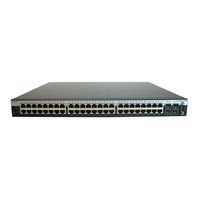
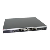
Enterasys B5G124-48P2 Quick Reference (2 pages)
Gigabit Ethernet Switch
Brand:
Enterasys
| Category:
Switch
| Size: 0.61 MB
Advertisement
Related Products
Enterasys B5G124-24
Enterasys B5G124-24P2
Enterasys B5G124-48
Enterasys B5K125-24
Enterasys B5K125-24P2
Enterasys B5K125-48
Enterasys B5K125-48P2
Enterasys SecureStack B2 B2G124-48P
Enterasys BL-69224ENT
Enterasys b5
Enterasys Categories
Switch
Network Router
Network Hardware
Wireless Access Point
Software
More Enterasys Manuals
Login
Sign In
OR
Sign in with Facebook
Sign in with Google
Upload manual
Upload from disk
Upload from URL