Sign In
Upload
Manuals
Brands
Endress+Hauser Manuals
Measuring Instruments
Ceraphant PTP31B
Endress+Hauser Ceraphant PTP31B Manuals
Manuals and User Guides for Endress+Hauser Ceraphant PTP31B. We have
3
Endress+Hauser Ceraphant PTP31B manuals available for free PDF download: Operating Instructions Manual
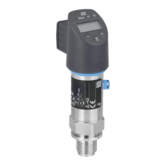
Endress+Hauser Ceraphant PTP31B Operating Instructions Manual (80 pages)
Process pressure measurement. Pressure switch for safe measurement and monitoring of absolute and gauge pressure
Brand:
Endress+Hauser
| Category:
Measuring Instruments
| Size: 1.35 MB
Table of Contents
Table of Contents
3
1 Document Information
5
Document Function
5
Symbols Used
5
Documentation
6
Terms and Abbreviations
7
Turn down Calculation
8
2 Basic Safety Instructions
9
Requirements Concerning the Staff
9
Designated Use
9
Workplace Safety
10
Operational Safety
10
Product Safety
10
3 Product Description
11
Product Design
11
Function
11
4 Incoming Acceptance and Product
12
Identification
12
Incoming Acceptance
12
Product Identification
13
Storage and Transport
13
5 Installation
15
Mounting Dimensions
15
Installation Conditions
15
Influence of the Installation Position
15
Mounting Location
16
Post-Installation Check
18
6 Electrical Connection
19
Connecting the Measuring Unit
19
Relay Switching Capacity
20
Connection Conditions
21
Connection Data
21
Post-Connection Check
21
7 Operation Options
22
Operation with an Operating Menu
22
Structure of the Operating Menu
22
Operation with Local Display
22
General Value Adjustment and Rejection of Illegal Entries
23
Navigation and Selection from List
23
Locking and Unlocking Operation
24
Navigation Examples
26
Status Leds
26
Resetting to Factory Settings (Reset)
26
8 Commissioning
27
Function Check
27
Enabling Configuration/Operation
27
Commissioning with an Operating Menu
27
Configuring Pressure Measurement (Only for Devices with a Current Output)
27
Performing Position Adjustment
29
Configuring Process Monitoring
32
Functions of Switch Output
32
Current Output
35
Application Examples
37
Configuring the Local Display
37
Protecting Settings from Unauthorized
38
Access
38
9 Diagnostics and Troubleshooting
39
Troubleshooting
39
Diagnostic Events
40
Behavior of the Device in the Event of a Fault
42
Response of Output to Errors
42
Behavior of the Device in the Event of a Voltage Drop
43
Behavior of the Device in the Event of an Incorrect Entry
43
Disposal
43
10 Maintenance
44
Exterior Cleaning
44
11 Repair
45
General Notes
45
Return
45
12 Overview of the Operating Menu
46
13 Description of Device Parameters
49
Switch Output 1 and Switch Output 2
49
Current Output
53
STL Value for 4 Ma (LRV)
53
STU Value for 20 Ma (URV)
53
EF Menu (Extended Functions)
54
Dr1 Switchback Delay Time, Output
54
Dr2 Switchback Delay Time, Output 2
54
Ds1 Switching Delay Time, Output
54
Ds2 Switching Delay Time, Output 2
54
Yes
54
HNO no Contact for Hysteresis Function
55
FNC NC Contact for Window Function
56
FNO no Contact for Window Function
56
GTL Pressure Applied for 4Ma (LRV)
56
HNC NC Contact for Hysteresis Function
56
GTU Pressure Applied for 20Ma (URV)
57
Yes
57
FCU Alarm Current
58
Max
58
HI Max Value (Maximum Indicator)
59
UNI Unit Changeover
59
LO Min Value (Minimum Indicator)
60
TAU Damping
61
DVA PV Display Measured Value
62
DRO Display Measured Value Rotated by 180
62
LCK Unlocking Code
62
• SP = Display Set Switch Point
62
COD Locking Code
63
DIAG Menu (Diagnosis)
64
LST Last Device Status
64
STA Current Device Status
64
DOF Display off
62
SM1 Simulation Output 1
64
14 Accessories
66
Weld-In Adapter
66
Process Adapter M24
66
M12 Plug Connectors
67
15 Technical Data
68
Input
68
Output
70
Performance Characteristics of Metallic
73
Process Isolating Diaphragm
73
Environment
75
Process
76
Index
77
Advertisement
Endress+Hauser Ceraphant PTP31B Operating Instructions Manual (92 pages)
Pressure switch for safe measurement and monitoring of absolute and gauge pressure
Brand:
Endress+Hauser
| Category:
Switch
| Size: 1.56 MB
Table of Contents
Table of Contents
3
1 Document Information
5
Document Function
5
Symbols Used
5
Documentation
6
Terms and Abbreviations
7
Turn down Calculation
8
Registered Trademarks
8
2 Basic Safety Instructions
9
Requirements Concerning the Staff
9
Designated Use
9
Workplace Safety
10
Operational Safety
10
Product Safety
10
3 Product Description
11
Product Design
11
Function
11
4 Incoming Acceptance and Product
13
Identification
13
Incoming Acceptance
13
Product Identification
14
Storage and Transport
14
5 Installation
16
Mounting Dimensions
16
Installation Conditions
16
Influence of the Installation Position
16
Mounting Location
17
Mounting Instructions for Oxygen Applications
19
Post-Installation Check
19
6 Electrical Connection
20
Connecting the Measuring Unit
20
Switching Capacity
22
Connection Data
22
Post-Connection Check
23
7 Operation Options
24
Operation with an Operating Menu
24
Operation with Local Display
25
General Value Adjustment and Rejection of Illegal Entries
26
Navigation and Selection from List
26
Locking and Unlocking Operation
28
Navigation Examples
30
Status Leds
30
Resetting to Factory Settings (Reset)
30
8 System Integration
31
Process Data
31
Reading out and Writing Device Data (ISDU - Indexed Service Data Unit)
32
Overview of Diagnostic Events
34
9 Commissioning
35
Function Check
35
Commissioning with an Operating Menu
35
Configuring Pressure Measurement
36
Performing Position Adjustment
38
Configuring Process Monitoring
40
Current Output
40
Application Examples
43
10 Diagnostics and Troubleshooting
44
Troubleshooting
44
Diagnostic Events
45
Behavior of the Device in the Event of a Fault
47
Signal on Alarm 4 to 20 Ma
47
Behavior of the Device in the Event of a Voltage Drop
48
Behavior of the Device in the Event of an Incorrect Entry
48
Resetting to Factory Settings (Reset)
48
11 Maintenance
48
Exterior Cleaning
49
12 Repairs
50
General Notes
50
Return
50
Disposal
50
Operating Menu
51
Overview of the Onsite Display Operating Menu
52
Menu
54
14 Overview of the IO-Link Operating
54
15 Description of Device Parameters
56
Ds2 Switching Delay Time, Output
69
Dr2 Switchback Delay Time, Output
69
Hno
69
Hnc
69
HI Max Value (Maximum Indicator)
71
LO Min Value (Minimum Indicator)
71
Revision Counter
71
LCK Unlocking Code
72
COD Locking Code
72
Display Measured Value
73
DRO Display Measured Value Rotated by 180
73
DOF Display off
73
Observation
74
16 Accessories
75
Weld-In Adapter
75
Process Adapter M24
75
M12 Plug Connectors
76
17 Technical Data
77
Input
77
Output
80
Performance Characteristics of Ceramic Process Isolating Diaphragm
83
Performance Characteristics of Metal Process Isolating Diaphragm
85
Environment
87
Process
88
Index
90
Endress+Hauser Ceraphant PTP31B Operating Instructions Manual (88 pages)
Brand:
Endress+Hauser
| Category:
Measuring Instruments
| Size: 1.61 MB
Table of Contents
Table of Contents
3
About this Document
5
Document Function
5
Symbols Used
5
Documentation
6
Terms and Abbreviations
7
Turn down Calculation
7
Registered Trademarks
8
Basic Safety Instructions
9
Requirements Concerning the Staff
9
Intended Use
9
Product Safety
10
Operational Safety
10
Workplace Safety
10
Product Description
11
Product Design
11
Operating Principle
11
Incoming Acceptance and Product
13
Identification
13
Incoming Acceptance
13
Product Identification
14
Storage and Transport
14
Mounting
16
Installation Conditions
16
Influence of Orientation
16
Mounting Location
17
Post-Mounting Check
19
Mounting Instructions for Oxygen Applications
19
Electrical Connection
20
Connecting the Measuring Unit
20
Connection Data
22
Post-Connection Check
23
Operation Options
24
Operation with Operating Menu
24
Operation with Local Display
25
General Value Adjustment and Rejection of Illegal Entries
26
Navigation and Selection from List
26
Locking and Unlocking Operation
28
Resetting to Factory Settings (Reset)
30
Navigation Examples
30
Status Leds
30
System Integration
31
Process Data
31
Reading out and Writing Device Data (ISDU - Indexed Service Data Unit)
32
Commissioning
39
Function Check
39
Commissioning with an Operating Menu
39
Configuring Pressure Measurement
40
Performing Position Adjustment
42
Configuring Process Monitoring
44
Current Output
45
Application Examples
47
Diagnosis and Troubleshooting
48
Troubleshooting
48
Diagnostic Events
49
Behavior of the Device in the Event of a Fault
51
Signal on Alarm 4 to 20 Ma
52
Behavior of the Device in the Event of a Voltage Drop
52
Behavior of the Device in the Event of an Incorrect Entry
53
Resetting to Factory Settings (Reset)
53
Maintenance
53
Exterior Cleaning
53
Return
54
Disposal
54
General Notes
54
Repair
54
Without Smart Sensor Profile
55
Operating Menu
55
With Smart Sensor Profile
57
Overview of the IO-Link Operating
60
Menu
60
Without Smart Sensor Profile
60
With Smart Sensor Profile
61
Overview of the Io-Link Operating Menu
62
Description of Device Parameters
63
Identification
63
Diagnosis
64
Parameter
66
SSC1.1 Config. Logic
76
SSC1.1 Config. Mode
76
SSC1.1 Param. SP2
76
SSC1.1 Config. Hyst
77
SSC1.2 Param. SP1
77
Switchback Delay Time, Output
77
Switching Delay Time, Output
77
SSC1.2 Config. Hyst
78
SSC1.2 Config. Logic
78
SSC1.2 Config. Mode
78
SSC1.2 Param. SP2
78
Switchback Delay Time, Output 2(Dr2)
79
Switching Delay Time, Output
79
HI Max Value
81
LO Min Value
81
Reset to Factory Settings (RES)
81
Revisioncounter (RVC)
81
Back-To-Box
82
Observation
83
Accessories
84
Flush Mount Pipe Connections M24
84
Process Adapter M24
84
Weld-In Adapter
84
M12 Plug-In Jack
85
Index
86
Advertisement
Advertisement
Related Products
Endress+Hauser Ceraphant PTP33B
Endress+Hauser Proline Prosonic Flow W
Endress+Hauser Proline Promag 51
Endress+Hauser Proline Promass P 300
Endress+Hauser Proline Promass 80F
Endress+Hauser Prosonic Flow 500-digital
Endress+Hauser Proline Prosonic Flow 92F HART
Endress+Hauser Proline Promass 200
Endress+Hauser Picomag IO-Link
Endress+Hauser PROFIBUS PA Levelflex FMP56
Endress+Hauser Categories
Measuring Instruments
Transmitter
Radar
Switch
Accessories
More Endress+Hauser Manuals
Login
Sign In
OR
Sign in with Facebook
Sign in with Google
Upload manual
Upload from disk
Upload from URL