Sign In
Upload
Manuals
Brands
Emerson Manuals
Transmitter
Rosemount Oxymitter 4000
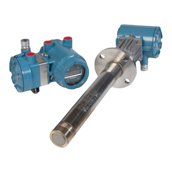
Emerson Rosemount Oxymitter 4000 Manuals
Manuals and User Guides for Emerson Rosemount Oxymitter 4000. We have
3
Emerson Rosemount Oxymitter 4000 manuals available for free PDF download: Reference Manual, Instruction Manual
Emerson Rosemount Oxymitter 4000 Reference Manual (194 pages)
Hazardous Area Oxygen Transmitter
Brand:
Emerson
| Category:
Transmitter
| Size: 47.33 MB
Table of Contents
Table of Contents
2
Essential Instructions
7
Preface
8
Definitions
9
Symbols
9
Note to Users
9
Description and Specifications
10
Components Checklist
10
System Overview
10
Scope
10
System Description
12
System Configuration
13
System Features
14
System Considerations
17
IMPS 4000 (Optional)
20
SPS 4001B (Optional)
20
MODEL 751 Remote Powered Loop LCD Display
20
Probe Options
21
Diffusion Elements
21
Abrasive Shield Assembly
22
Specifications
24
Range
24
Temperature Limits
24
Probe Lengths
24
Mounting and Mounting Position
24
Materials
24
Calibration Gas Mixtures
24
Recommended Calibration Gas Flow
24
Pollution Degree
25
Over Voltage Category
25
Relative Humidity
25
Signals
25
Power Requirements
25
Certifications
25
Hazardous Area Oxymitter 4000 with Integral Electronics with Process End Flame Arrestor
25
Hazardous Area Oxymitter with Remote Electronics with Process End Flame Arrestor
25
Hazardous Area Oxymitter 4000 with Integral Electronics Without Process End Flame Arrestor
26
Hazardous Area Oxymitter with Remote Electronics Without Process End Flame Arrestor
26
Atex/Iecex Special Conditions for Safe Use
26
CSA Special Conditions for Safe Use
27
Installation
35
Mechanical Installation
36
Selecting Location
36
Probe Installation
36
Remote Electronics Installation
44
Electrical Installation with Integral Electronics
44
Connect Line Voltage
45
Electrical Installation with Remote Electronics
47
Connect Line Voltage
48
4-20 Ma Signal
48
World Class 3000 Intelligent Field Transmitter Setup
51
The Yokogawa ZA8C and AV8C Convertor Electronics Setup
52
Pneumatic Installation
54
Reference Air Package
54
Calibration Gas
55
IMPS 4000 Connections
55
SPS 4001B Connections
55
Configuration of Hazardous Area Oxymitter 4000 with Membrane Keypad
56
Verify Installation
56
Mechanical Installation
56
Terminal Block Wiring
56
Hazardous Area Oxymitter 4000 Configuration
57
Recommended Configuration
61
Configuration of Hazardous Area Oxymitter 4000 with LOI
63
Verify Installation
63
Mechanical Installation
63
Terminal Block Wiring
63
Hazardous Area Oxymitter 4000 Configuration
64
Logic I/O
66
Recommended Configuration
68
Startup and Operation of Hazardous Area Oxymitter 4000 with Membrane Keypad
69
Power up
69
Startup Display
69
Operating Display
69
Error
70
Keypad
70
Reference Air
70
Operation
70
Overview
70
Startup and Operation of Hazardous Area Oxymitter 4000 with LOI
73
Power up
73
Startup Display
73
Operating Display
73
Error
73
Loi
73
Reference Air
73
Startup Oxymitter 4000 Calibration
75
Navigating the Local Operator Interface
75
Overview
75
Lockout
75
LOI Key Designations
76
LOI Menu Tree
76
Hazardous Area Oxymitter 4000 Setup at the LOI
78
System/Calibration Setup
78
Reset Values
79
O2 Output Tracks
79
O2 Cal Interval
79
O2 Next Cal
79
Gas Time
79
Purge Time
79
Auto Calib
79
System/Input/Output
79
System/Parameters
80
Slope
80
O2 Constant
80
O2 T90 Time
80
Auto Tune
80
Lockout Time
80
Revert Time
80
Luminance
80
System/Status
81
Alarms
81
PID Parameter
81
Reset Device
81
System/Software
81
Sensor Data
81
Temperatures
81
LOI Installation
81
Oxymitter 4000 Test Points
82
Remote Powered Loop LCD Display (Optional)
82
Hart/Ams
83
Overview
83
HART Communicator Signal Line Connections
84
Method 1, for Load Resistance ≥ 250 Ohms
84
Method 2, for Load Resistance < 250 Ohms
84
HART Communicator PC Connections
86
Off-Line and On-Line Operations
86
Logic I/O Configurations
87
HART/AMS Menu Tree
87
HART Communicator O Cal Method
91
Cal Method
92
D/A Trim Procedure
93
LOI Menu
93
Troubleshooting
94
Overview
94
General
96
Grounding
96
Electrical Noise
96
Loose Integrated Circuits
96
Electrostatic Discharge
96
Alarm Indications
96
Alarm Contacts
97
SPS 4001B and IMPS 4000, 1-4 Probes
98
Additional IMPS 4000 Alarm Contacts
98
Identifying and Correcting Alarm Indications
98
Fault 1, Open Thermocouple
100
Fault 2, Shorted Thermocouple
102
Fault 3, Reversed Thermocouple Wiring or Faulty PC Board
104
Fault 4, A/D Comm Error
106
Fault 4, Open Heater
108
Fault 6, High High Heater Temp
110
Fault 7, High Case Temp
112
Fault 8, Low Heater Temp
114
Fault 9, High Heater Temp
116
Fault 10, High Cell MV
118
Fault 11, Bad Cell
120
Fault 12, Eeprom Corrupt
122
Fault 13, Invalid Slope
124
Fault 14, Invalid Constant
126
Fault 15, Last Calibration Failed
128
Heater Not Open, but Unable to Reach 1357 °F (736 °C) Set
130
Point
130
Calibration Passes, but Still Reads Incorrectly
130
Probe Passes Calibration, but Still Appears to Read High
130
Probe Passes Calibration, but Still Appears to Read Low
131
How Do I Detect a Plugged Diffuser
131
Calibration Record for Rosemount In-Situ O Probe
132
Maintenance and Service
133
Overview
133
Calibration with Keypad
133
Automatic Calibration
134
Semi-Automatic Calibration
135
Manual Calibration with Membrane Keypad
136
Calibration with LOI
138
Hazardous Area Oxymitter 4000 Repair
139
Removal and Replacement of Probe
140
Electronic Assembly Replacement
144
Terminal Block Replacement
146
Fuse Replacement
146
Entire Probe Replacement (Excluding Electronics)
147
Heater Strut Replacement
148
Cell Replacement
150
Ceramic Diffusion Element Replacement
153
Replacement Parts
156
Probe Replacement Parts
156
Electronics Replacement Parts
159
Upgrading Oxymitter DR to Full Oxymitter
160
A-1 Upgrade Procedure
160
A-2 Notes
162
Optional Accessories
163
By-Pass Packages
163
IMPS 4000 Intelligent Multiprobe Test Gas Sequencer
164
SPS 4001 Single Probe Autocalibration Sequencer
165
Calibration Gas
166
Safety Data
167
Warranty
193
Advertisement
Emerson Rosemount Oxymitter 4000 Instruction Manual (188 pages)
Oxygen
Brand:
Emerson
| Category:
Transmitter
| Size: 4.29 MB
Table of Contents
Table of Contents
5
IM-106-340, Rev
8
Essential Instructions
9
SECTION I
11
Preface
12
Symbols
12
Definitions
12
What You Need to Know
13
Can You Use the Quick Start Guide
15
Quick Start Guide for Oxymitter 4000 Systems
16
Quick Reference Guide Manual Calibration Instructions
17
HART Communicator Fast Key Sequences
18
Section 1
19
Component Checklist
19
Description and Specifications
19
System Overview
19
Scope
19
System Description
21
System Configuration
22
System Features
22
Handling the Oxymitter 4000
26
System Considerations
27
IMPS 4000 (Optional)
30
SPS 4001B (Optional)
30
Mounting
30
Operation
30
Model 751 Remote Powered Loop LCD Display
31
Probe Options
31
Diffusion Elements
31
Specifications
34
Section 2
39
Verify Installation
39
Configuration of Oxymitter 4000 with Membrane Keypad
39
Terminal Block Wiring
39
Oxymitter 4000 Configuration
40
Recommended Configuration
44
SECTION 3 Mechanical Installation
46
Mechanical Installation
46
Installation Selecting Location
46
Probe Installation
46
Remote Electronics Installation
53
Electrical Installation (with Integral Electronics)
54
Electrical Installation (with Remote Electronics)
57
Install Interconnecting Cable
60
Pneumatic Installation
60
IMPS 4000 Connections
62
SPS 4001B Connections
62
Verify Installation
63
Mechanical Installation
63
Terminal Block Wiring
63
Oxymitter 4000 Configuration
64
Logic I/O
66
Recommended Configuration
68
Power up
69
Operation
70
Overview
70
Power up
73
Start up Oxymitter 4000 Calibration
75
Navigating the Local Operator Interface
75
Overview
75
Lockout
75
LOI Key Designations
76
LOI Menu Tree
76
Oxymitter 4000 Setup at the LOI
78
LOI Installation
81
Oxymitter 4000 Test Points
82
Remote Powered Loop LCD Display (Optional)
82
Overview
83
HART Communicator Signal Line Connections
84
HART Communicator PC Connections
84
Off-Line and On-Line Operations
86
Logic I/Oconfigurations
86
HART/AMS Menu Tree
86
HART Communicator O
90
Defining a Timed Calibration Via HART
91
D/A Trim Procedure
91
Overview
93
General
95
Alarm Indications
95
Alarm Contacts
96
Identifying and Correcting Alarm Indications
97
Heater Not Open, but Unable to Reach 736°C Setpoint
114
Calibration Passes, but Still Reads Incorrectly
114
Overview
117
Calibration with Keypad
117
Automatic Calibration
118
Semi-Automatic Calibration
119
Manual Calibration with Membrane Keypad
119
Calibration with LOI
121
Oxymitter 4000 Repair
123
Removal and Replacement of Probe
123
Probe Replacement Parts
137
Electronics Replacement Parts
143
HART Handheld 375 Communicator
145
Asset Management Solutions (AMS)
146
By-Pass Packages
146
IMPS 4000 Intelligent Multiprobe Test Gas Sequencer
147
SPS 4001B Single Probe Autocalibration Sequencer
148
O 2 Calibration Gas
149
Catalyst Regeneration
150
Oxybalance Display and Averaging System
150
Safety Instructions
154
APPENDIX A Safety Instructions
176
Safety Data Sheet for Ceramic Fiber Products
176
Returning Material
183
Emerson Rosemount Oxymitter 4000 Reference Manual (198 pages)
Hazardous Area Oxygen Transmitter
Brand:
Emerson
| Category:
Transmitter
| Size: 5.43 MB
Table of Contents
Table of Contents
5
Chapter 1 Description and Specifications
9
Components Checklist
9
Overview
17
Measurement
17
Configuration
18
Features
19
System Considerations
22
Optional Rosemount IMPS 4000
30
Optional Rosemount SPS 4001B
30
Rosemount 751 Remote Powered Loop LCD Display
30
Probe Options
31
Specifications
33
Electrical Specifications
34
Physical Specifications
35
Chapter 2 Install
37
Mechanical Installation
37
Electrical Installation with Integral Electronics
51
Electrical Installation with Remote Electronics
58
Pneumatic Installation
65
Rosemount ™ IMPS 4000 Connections
68
Rosemount SPS 4001B Connections
68
Chapter 3 Configure Transmitter with Membrane Keypad
69
Verify Installation
69
Mechanical Installation
69
Wire Terminal Block
69
Configuration
70
Logic I/O
73
Recommended Configuration
74
Chapter 4 Configure Transmitter with LOI
77
Verify Installation
77
Mechanical Installation
77
Wire Terminal Block
77
Configuration
79
Logic I/O
82
Recommended Configuration
82
Chapter 5 Start up and Operate Transmitter with Membrane Keypad
85
Power up
85
Operate
88
Chapter 6 Start up and Operate Transmitter with LOI
91
Power up
91
Navigating the Local Operator Interface
95
LOI Key Designations
96
LOI Menu Tree
96
Setup at the LOI
98
System/Parameters
99
System/Status
100
LOI Installation
101
Test Points
101
Remote Powered Loop LCD Display (Optional)
102
Chapter 7 HART ® /AMS
103
Overview
103
HART Communicator Signal Line Connections
103
Connect HART ® Communicator to a PC
107
Off-Line and On-Line Operations
107
Logic I/O Configurations
107
HART ® Menu Tree
109
Calibrate O with HART
111
Automatically Calibrate with HART
113
D/A Trim
113
Chapter 8 Troubleshoot
115
Overview
115
Factors to Consider When Troubleshooting
116
Alarm Indications
117
Alarm Contacts
118
Identify and Correct Alarm Indications
119
Heater Not Open, but Unable to Reach 1357 °F (736 °C) Setpoint
145
Calibration Passes, but Still Reads Incorrectly
146
Chapter 9 Maintenance and Service
149
Overview
149
Calibrate
149
Repair
157
Chapter 10 Replacement Parts
173
Probe Replacement Parts
173
Electronics Replacement Parts
175
Appendix A Upgrade Rosemount Oxymitter DR to Full Oxymitter
177
Appendix B Optional Accessories
181
Rosemount ™ By-Pass Package
181
Rosemount ™ IMPS 4000 Intelligent Multiprobe Test Gas Sequencer
181
Rosemount ™ SPS 4001B Single Probe Autocalibration Sequencer
182
Appendix C Safety Instructions
185
Appendix D Safety Data Sheet for Ceramic Fiber Products
187
Identification
187
Physical Data
187
Appendix E Rosemount ™ Oxymitter ™ Product Certifications
189
European Directive Information
189
Ordinary Location Certification
189
Installing Equipment in North America
189
Certification
189
Rosemount ™ XI, X-Stream XI Remote Interface, for General Locations Certification
191
Appendix F Declaration of Conformity
193
Appendix G China Rohs Table
197
Advertisement
Advertisement
Related Products
Emerson Rosemount
Emerson Rosemount 3051 Series
Emerson Rosemount TCL
Emerson Rosemount 2051 Wireless Series
Emerson Rosemount Ultrasonic 3108
Emerson Rosemount5081
Emerson Rosemount X-well 648
Emerson Rosemount 3108
Emerson Rosemount 702 Series
Emerson Rosemount 520
Emerson Categories
Controller
Control Unit
Transmitter
Measuring Instruments
Fan
More Emerson Manuals
Login
Sign In
OR
Sign in with Facebook
Sign in with Google
Upload manual
Upload from disk
Upload from URL