Sign In
Upload
Manuals
Brands
Emerson Manuals
Control Unit
LiebertChallenger ITR
Emerson LiebertChallenger ITR Manuals
Manuals and User Guides for Emerson LiebertChallenger ITR. We have
1
Emerson LiebertChallenger ITR manual available for free PDF download: User Manual
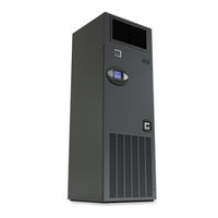
Emerson LiebertChallenger ITR User Manual (100 pages)
Intelligent Communications & Monitoring for Liebert Challenger 3000, Liebert Challenger ITR and Liebert DS
Brand:
Emerson
| Category:
Control Unit
| Size: 3.18 MB
Table of Contents
Table of Contents
3
1 Introduction
7
Features
7
Figure 1 Liebert Icom Components
7
2 Liebert Icom Display Components and Functions
8
Figure 2 Liebert Icom Display Components
8
Table 1 Keyboard Icons and Functions
9
Figure 3 Status Menu, Large Display, Graphical View
10
Figure 4 Liebert Icom Default Screen Symbols
10
Navigating through the Liebert Icom Menus
11
Control Interface
11
Accessing Submenus
11
Figure 5 Menu Tree-Small Display, Stand-Alone or Networked
11
Entering a Password
12
Figure 6 Entering a Password
13
Figure 7 Menu Tree-Large Display, Stand-Alone
13
Viewing Multiple Units with a Networked Large Display
14
Figure 8 Menu Tree-Large Display, Networked
14
Figure 9 User Menu Icons
15
User Menu Icons
15
Figure 10 Service Menu Icons
16
Service Menu Icons
16
3 Operation
18
Single Unit Functions
18
Unit/Fan Control
18
Figure 11 Start-Stop Priority Switches
18
General Compressor Requirements
21
Compressor Timing-Short-Cycle Protection
22
Compressor Sequencing on Two-Compressor Units
22
Motorized Ball Valve in Digital Scroll Units
22
MBV Operation after Compressor Is Turned off
23
Service Offset-Changing System Pressure Settings
23
Temperature Control-Single Source Cooling (no Extra Cooling Coil)
24
Temperature Proportional Band
24
Figure 12 Temperature Proportional Band
24
Compressor Control
25
Figure 13 One Single-Step Compressor Without Unloaders
25
Figure 14 Two Single-Step Compressors Without Unloaders or One Compressor with an Unloader
25
Figure 15 Two Compressors with Unloaders (Four-Step)
26
Figure 16 Digital Scroll Capacity Modulation, 10-100% Variable
26
Figure 17 Single and Dual Digital Scroll Compressor Activation Points
27
Chilled Water Control
28
Figure 18 DIP Switch Locations on Liebert Icom Control Board
28
Temperature Control-Second Cooling Source
29
Differential Temperatures / Controls (Comparator Circuit)
29
Figure 19 Chilled Water Valve Control (Example: Cooling)
29
Figure 20 Second Cooling Source and Two-Step Compressorized Cooling
30
Temperature Control-Reheat
31
Three-Stage Electric, Hot Gas and Hot Water Reheat
31
SCR Reheat
31
Figure 21 Three-Stage Heating
31
Table 4 Reheat Configuration Types
31
Figure 22 Two Single-Step Compressors with SCR Reheat Set to Tight Mode
32
Humidity Control
33
Figure 23 Two Single-Step Compressors with SCR Reheat Set to Standard Mode
33
Figure 24 Humidity Proportional Band
33
Humidification
34
Table 5 Parameters for Infrared Humidifier Control
34
Dehumidification
35
Table 6 Dehumidification with Comp Settings
35
Control Types
36
Temperature and Humidity Control Types
36
Humidity Sensor Reading Control Types
37
Figure 25 Placing Temperature and Temperature/Humidity Sensors
38
Supply Control
39
Supply Air
39
Event Types and Properties
40
Table 7 Possible Event Settings-Some Events Not Available in All Units
41
High- and Low-Temperature and Humidity Events
42
User Inputs
42
Customer Inputs
42
Table 8 Customer Inputs
42
Liebert Icom-DO
43
Table 9 Alarm Mapping
43
Possible Event Notifications
44
Wellness-Next Maintenance Calculation
44
Table 10 Event Notifications-Large or Small Display
44
Calculation of Next Maintenance and Diagnostics
45
4 Teamwork
47
Teamwork Modes
47
Application of Teamwork Modes
47
No Teamwork
47
Teamwork Mode 1
47
Figure 26 Teamwork Mode 1 with Two Cooling Units
48
Teamwork Mode 2
49
Standby-Rotation
49
5 Installing a Liebert Icom Unit - to -Unit Network
50
Placement of Cooling Units
50
Balancing Operating and Standby Units
50
Figure 27 Standby Unit Layout Example-10 Precision Cooling Units in Room
50
U2U Hardware: Cables and Network Switch
51
Wiring for Unit-To-Unit Communications-U2U
52
Wiring a Liebert Icom U2U Network
52
Figure 28 Connecting Two Cooling Units, each with a Small Display Using a Crossover Ethernet Cable
52
Table 11 Sample Liebert Icom Network Configurations
52
Figure 29 U2U Network Setup Diagram
53
Figure 30 Wiring a Small Display for Stand-Alone Operation
54
Figure 31 Wiring a Small Display for U2U Network Operation
55
Figure 32 Wiring a Large Display for U2U Network Operation
56
Figure 33 Liebert Vnsa with Optional Remote Large Display
57
Table 12 Ports Available for Connecting Liebert Icom Control Devices
57
6 External Communications-Building Management Systems, Liebert Sitescan
58
7 User Menu Parameters
59
Figure 34 User Menu Icons
59
Figure 35 Setpoints Parameters Screen
59
Figure 36 Set Alarms Screen
60
Figure 37 Sensor Data Screen
62
Figure 38 Sensor Data Screen - Page 2 (Return Only)
63
Figure 39 Display Setup Parameters Screen
64
Figure 40 Total Run Hours Parameters Screen
65
Figure 41 Sleep Mode Parameters Screen
65
8 Service Menu Parameters
66
Figure 42 Service Menu Main Screen
66
Figure 43 Setpoints Parameters Screen
67
Figure 44 Setpoints Parameters Screen
68
Figure 45 Setpoints Parameters Screen
69
Figure 46 Setpoints Parameters Screen
70
Figure 47 Setpoints Parameters Screen
71
Figure 48 Setpoints Parameters Screen
72
Table 13 Unit Diary Parameters
72
Figure 49 Standby Settings / Lead-Lag Parameters Screen
73
Figure 50 Wellness Basic Settings Screen
74
Figure 51 Wellness Motor Settings Parameters Screen
75
Figure 52 Wellness Compressor 1 Settings Parameters Screen
75
Figure 53 Wellness Compressor 1 Settings Parameters
76
Figure 54 Wellness Electric Heater 1 Settings Parameters Screen
76
Figure 55 Wellness Electric Heater 2 Settings Parameters Screen
77
Figure 56 Wellness Electric Heater 3 Settings Parameters Screen
77
Figure 57 Wellness Humidifier Settings Parameters Screen
78
Figure 58 Diagnostics / Service Mode Parameters Screen
79
Figure 59 Diagnostics / Service Mode Parameters Screen
80
Figure 60 Diagnostics / Service Mode Parameters Screen
81
Figure 61 Diagnostics / Service Mode Parameters Screen
82
Figure 62 Diagnostics / Service Mode Parameters Screen
83
Figure 63 Diagnostics / Service Mode Parameters Screen
84
Figure 64 Diagnostics / Service Mode Parameters Screen
84
Figure 65 Set Alarms Parameters Screen
85
Figure 66 Set Alarms Parameters Screen
86
Figure 67 Set Alarms Parameters Screen
86
Figure 68 Set Alarms Parameters Screen
87
Figure 69 Set Alarms Parameters Screen
87
Figure 70 Set Alarms Parameters Screen
88
Figure 71 Set Alarms Parameters Screen
88
Figure 72 Icom-DO Overview and Override
89
Figure 73 Icom-DO Events Setup - Page 2
89
Figure 73 Icom-DO Events Setup
90
Figure 74 Icom-DO Events Setup
90
Figure 75 Sensor Calibration / Setup Parameters
90
Figure 76 Sensor Calibration / Setup Parameters
91
Figure 77 Sensor Calibration / Setup Parameters
92
Figure 78 System / Network Setup Parameters-Large Display Only System
92
Figure 79 System / Network Setup Parameters-Large Display Only System
93
Figure 80 System/Network Setup Parameters Unit
94
Figure 81 System/Network Setup Parametersunit
95
Figure 82 Options Setup Parameters
96
Figure 83 Options Setup Parameters
97
Figure 84 Options Setup Parameters
98
Table 14 Service Contact Info Parameters
99
Advertisement
Advertisement
Related Products
Emerson Liebert DS
Emerson Liebert iCOM
Emerson Liebert Challenger ITR
Emerson Liebert CW
Emerson Liebert CRV
Emerson Liebert Precision Cooling
Emerson Liebert.CRV+
Emerson Liebert.CRV+ Series
Emerson Liebert eXM
Emerson Liebert PEX+ Series
Emerson Categories
Controller
Control Unit
Transmitter
Measuring Instruments
Fan
More Emerson Manuals
Login
Sign In
OR
Sign in with Facebook
Sign in with Google
Upload manual
Upload from disk
Upload from URL