Sign In
Upload
Manuals
Brands
Emerson Manuals
Control Unit
Fisher FLOBOSS 407
Emerson Fisher FLOBOSS 407 Manuals
Manuals and User Guides for Emerson Fisher FLOBOSS 407. We have
1
Emerson Fisher FLOBOSS 407 manual available for free PDF download: Instruction Manual
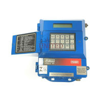
Emerson Fisher FLOBOSS 407 Instruction Manual (200 pages)
Field Automation Systems, FLOW MANAGER
Brand:
Emerson
| Category:
Control Unit
| Size: 1.96 MB
Table of Contents
Table of Contents
3
Section 1 - General Information
7
Scope of Manual
7
Display
7
Figure A-1. Lightning Protection Module
7
1.2 Section
8
Product Overview
8
Environmental Requirements
8
Related Documents and Compatibility
10
Section Contents
8
Installation Guidelines
11
Site Requirements
11
Compliance with Hazardous Area Standards
12
Grounding Installation Requirements
13
Power Installation Requirements
13
I/O Wiring
14
Electrical Isolation
14
Power Consumption Calculation
15
Determining I/O Channel Power Consumption
15
Radio Modem
16
Determining Radio Power Consumption
18
Totaling Power Requirements
18
Startup and Operation
19
Startup
19
Operation
19
Keypad Operation
20
Service Bulletins
21
Section 2 - the Floboss 407 Base Unit
23
Scope
23
Product Description
24
Functionality
24
Processor Board Description
27
Figure 2-1. Processor and Termination Boards
28
Floboss 407 Termination Board Description
30
Installation
33
Installing the Floboss 407 Unit
33
Figure 2-2. Floboss 407 Outline and Mounting Dimensions
34
Installing Floboss 407 Options and Accessories
34
Figure 2-3. Padlock Adapter Installation
35
Connecting the Floboss 407 to Wiring
36
Connecting Ground Wiring
36
Connecting Main Power Wiring
36
Built-In Analog Input Wiring
37
Figure 2-4. Power Wiring Connections
37
Built-In Pulse Input Wiring
38
Figure 2-5. Current Signal on Built-In Analog Input
38
Figure 2-6. Voltage Signal on Built-In Analog Input
38
Connecting Communications Wiring
39
Figure 2-7. Externally-Powered Built-In Pulse Input
39
Figure 2-8. Floboss-Powered Built-In Pulse Input
39
Figure 2-9. Operator Interface, COM1, and COM2 Ports
40
Troubleshooting and Repair
41
Multi-Variable Sensor Wiring
41
LED Indicators
41
Figure 2-10. Floboss 407 Indicator Locations
42
Backup Procedure before Removing Power
43
After Installing Components
44
Cold Start
45
Warm Start
45
Fuses
46
RAM Backup and Real-Time Clock Battery
47
Calibrating the Board Temperature Input
48
Testing the Built-In Analog Input Channels
48
Testing the Built-In Pulse Input Channel
49
Replacing the Processor Board
50
Replacing the Termination Board
51
Replacing the Flash ROM
53
Specifications
54
Keypad and Display Replacement
54
Integral MVS Replacement
54
Section 3 - Input/Output Modules
57
Scope
57
Product Descriptions
58
Analog Input Loop and Differential Modules
59
Figure 3-1. Typical I/O Module
59
Analog Input Source Module
60
Analog Output Source Module
60
Discrete Input Source and Isolated Modules
60
Discrete Output Source and Isolated Modules
60
Discrete Inputs
60
Discrete Output Relay Module
61
Pulse Input Source and Isolated Modules
61
Slow Pulse Input Source and Isolated Modules
61
HART Interface Module
62
Low-Level Pulse Input Module
62
RTD Input Module
62
Initial Installation and Setup
63
Calibrating an I/O Module
63
Connecting the I/O Modules to Wiring
64
Analog Input Loop Module
64
Figure 3-2. AI Loop Module Field Wiring for Current Loop Devices
64
Figure 3-3. AI Loop Module Field Wiring for Voltage Devices
65
Analog Input Differential Module
66
Figure 3-4. AI Differential Module Field Wiring for Low Voltage Devices
66
Figure 3-5. AI Differential Module Field Wiring for Higher Voltage Devices
66
Figure 3-6. AI Differential Module Field Wiring for Current Loop Devices
67
Analog Input Source Module
68
Figure 3-7. AI Source Module Field Wiring for Voltage Devices
68
Figure 3-8. AI Source Module Field Wiring for Current Loop Devices
68
Analog Output Source Module
69
Figure 3-10. Analog Output Source Module Field Wiring for Voltage Devices
69
Figure 3-9. Analog Output Source Module Field Wiring for Current Loop Devices
69
Discrete Input Source Module
70
Figure 3-11. Discrete Input Source Module Field Wiring
70
Discrete Input Isolated Module
71
Figure 3-12. Discrete Input Isolated Module Field Wiring
71
Discrete Output Source Module
72
Figure 3-13. Discrete Output Source Module Field Wiring
72
Discrete Output Isolated Module
73
Figure 3-14. Discrete Output Isolated Module Field Wiring
73
Figure 3-15. Discrete Output Relay Module Field Wiring
74
Figure 3-16. Pulse Input Source Module Field Wiring
75
Pulse Input Source Module
75
Figure 3-17. Pulse Input Isolated Module Field Wiring
76
Pulse Input Isolated Module
76
Figure 3-18. Slow Pulse Input Source Module Field Wiring
77
Figure 3-19. Slow Pulse Input Isolated Module Field Wiring
78
Slow Pulse Input Isolated Module
78
Figure 3-20. Low-Level Pulse Input Module Field Wiring Schematic
79
Low-Level Pulse Input Module
79
RTD Input Module
80
Decade Box
80
Figure 3-21. Calibration Setup
80
Figure 3-22. RTD Input Module Field Wiring for Two-Wire Rtds
82
Figure 3-23. RTD Input Module Field Wiring for Three-Wire Rtds
82
Figure 3-24. RTD Input Module Field Wiring for 4-Wire RTD with Compensation Loop
83
Figure 3-25. Field Wiring for 4-Wire, Single Element
83
Figure 3-26. Field Wiring for a HART Interface Module
84
HART Interface Module
84
Troubleshooting and Repair
85
Removal, Addition, and Replacement Procedures
93
Impact on I/O Point Configuration
93
Removing/Installing an I/O Module
94
I/O Module Specifications
96
Section 4 - Communications Cards
111
Figure 4-2. EIA-422/485 Serial Communications Card
111
Figure 4-4. Leased-Line Modem Communications Card
111
Figure 4-5. Dial-Up Modem Communications Card
111
Serial Communications Card
112
Figure 4-1. EIA-232 Serial Communications Card
112
Control
115
Product Descriptions
111
Scope
111
Initial Installation and Setup
118
Installing Communications Cards
118
Figure 4-6. Communications Card Location
119
Setting Jumpers
119
Setting Attenuation Levels
120
Connecting Communication Cards to Wiring
121
Communications Card Wiring
122
Figure 4-7. EIA-232 Wiring Schematic
122
EIA-422/485 Communications Card Wiring
123
Figure 4-8. EIA-422 Wiring Schematic
123
Figure 4-9. EIA-485 Wiring Schematic
123
Leased-Line Communications Card Wiring
125
Figure 4-11. Leased-Line Modem Wiring Schematic
126
Dial-Up Modem Communications Card Wiring
127
Dsr
127
Dtr
127
Figure 4-12. Dial-Up Modem Wiring Schematic
127
Troubleshooting and Repair
128
Replacing a Communications Card
128
Communications Card Specifications
130
Section 5 - Display and Keypad
135
Product Description
135
Control
135
Day Hist
135
Edit Mode
135
Enclosure
135
Figure 5-1. Floboss 407 Display and Keypad
136
Display off
137
Figure 5-2. Keypad Layout
137
Scope
135
Keypad Functions
138
Normal Mode
138
Alt Mode
138
Figure 5-3. Operations Key
138
I/O Point
139
Display of Parameters
143
Arrow Keys
143
Figure 5-4. General Display Format
143
Flow Rates
144
I/O Detail
144
I/O Summary
144
Alarms
145
Figure 5-5. User List Display
145
Flow Comp
145
Meter Config
145
User List Keys
145
Figure 5-6. Alarm Summary Display
146
Figure 5-7. Min/Max History List Format
146
Figure 5-8. Min/Max History List Example
146
Figure 5-9. Min/Max History Minimum Value Example
146
Min/Max History
146
Figure 5-10. Min/Max History Maximum Value Example
147
Figure 5-11. Min/Max History Current Value Example
147
Figure 5-12. Minute History List Format
147
Figure 5-13. Minute History List Example
147
Minute History
147
Figure 5-14. Minute History Value Example
148
Figure 5-15. Hour History List Format
148
Figure 5-16. Hour History List Example
148
Hour History
148
Figure 5-17. Hour History Value Example
149
Comm Ports
150
Help
150
Security
151
Logging off the LCD
151
Continually Displaying the Last Parameter
151
Troubleshooting and Repair
152
Appendix A - Lightning Protection Module
153
Scope
153
Product Description
153
Initial Installation
154
Figure A-2. Typical Lighting Protection Module Installation
154
Connecting the LPM to Wiring
155
Troubleshooting and Repair
156
Specifications
156
Appendix B - Multi-Variable Sensors
157
Description
157
Differential Pressure
157
Figure B-1. MVS101R Multi-Variable Sensor
158
Figure B-2. MVS205R Multi-Variable Sensor
158
This Appendix Describes the Multi-Variable Sensor (MVS) Devices, Which Provide Differential Pressure
159
Scope
157
Figure B-3. Floboss 407 and Integral MVS Outline and Mounting Dimensions
159
MVS Mounting
159
Figure B-4. Pipe Mounting of Floboss 407 with Integral MVS
160
Figure B-5. MVS101R Mounting
161
Figure B-6. MVS205R Pipe Mounting
162
Figure B-7. MVS205R Panel Mounting
162
Field Wiring
163
Figure B-8. Signal Hook-Up for a Integral MVS
163
Figure B-9. Wiring the MVS101R
165
Figure B-11. Typical RTD Installation for MVS101
167
MVS Lightning Protection
167
RTD Wiring
167
Figure B-12. RTD Assembly Details
168
Configuration
169
Calibration
170
Down Arrow
170
Enter
171
MVS Troubleshooting and Repair
174
MVS Displays Letters Instead of Numbers
174
Specifications
175
Appendix C - I/O Simulation
177
Scope
177
Analog Outputs to Analog Inputs
177
Discrete Outputs
177
Figure C-1. Current Loop - AO Source Module to AI Loop Module
177
Analog Outputs to a Meter
178
Current Loop
178
Figure C-3. Voltage Input - AO Source Module to AI Differential Module
178
Discrete Outputs to Discrete Inputs
179
Discrete Outputs to Pulse Inputs
180
Potentiometer to Analog Inputs
181
Switch to Discrete Inputs
182
Switch to Pulse Inputs
183
Glossary of Terms
185
Duty Cycle
186
Advertisement
Advertisement
Related Products
Emerson Anderson Greenwood Type 443
Emerson Anderson Greenwood Type 453
Emerson Anderson Greenwood Type 463
Emerson Anderson Greenwood Type 449
Emerson Anderson Greenwood Type 459
Emerson Anderson Greenwood Type 469
Emerson ANDERSON GREENWOOD 4142HF
Emerson ANDERSON GREENWOOD 4020HP
Emerson FISHER Enardo 450 Series
Emerson Rosemount 400VP
Emerson Categories
Controller
Control Unit
Transmitter
Measuring Instruments
Fan
More Emerson Manuals
Login
Sign In
OR
Sign in with Facebook
Sign in with Google
Upload manual
Upload from disk
Upload from URL