Sign In
Upload
Manuals
Brands
Daikin Manuals
Air Conditioner
Super Multi NX B series
Daikin Super Multi NX B series Manuals
Manuals and User Guides for Daikin Super Multi NX B series. We have
1
Daikin Super Multi NX B series manual available for free PDF download: Service Manual
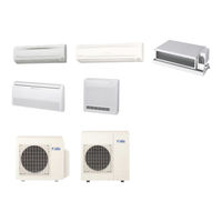
Daikin Super Multi NX B series Service Manual (302 pages)
Brand:
Daikin
| Category:
Air Conditioner
| Size: 9.92 MB
Table of Contents
Table of Contents
3
Introduction
8
Safety Cautions
8
Caution in Repair
8
Cautions Regarding Products after Repair
9
Inspection after Repair
10
Using Icons
11
Using Icons List
11
Part 1 List of Functions
12
List of Functions
13
Cooling Only Models
13
Heat Pump Models
21
Part 2 Specifications
30
Indoor Units - Cooling Only
31
Duct Connected Type
39
Floor Standing Type
44
Outdoor Units - Cooling Only
45
Indoor Units - Heat Pump
52
Outdoor Units - Heat Pump
66
Part 3 Printed Circuit Board Connector Wiring Diagram
72
Printed Circuit Board Connector Wiring Diagram
73
Wall Mounted Type 25 / 35 Class
73
Wall Mounted Type 50 / 60 / 71 Class
76
Control Pcb (Indoor Unit)
77
Signal Receiver Pcb
77
Floor / Ceiling Suspended Dual Type
78
Duct Connected Type
80
Floor Standing Type
81
Outdoor Units
83
Part 4 Function and Control
84
Main Functions
85
Frequency Principle
85
Power-Airflow Dual Flaps, Wide Angle Louvers and Auto-Swing
87
Fan Speed Control for Indoor Units
88
Programme Dry Function
89
Automatic Operation
90
Night Set Mode
91
Intelligent Eye
92
Home Leave Operation
94
Inverter Powerful Operation
95
Other Functions
96
Function of Main Structural Parts
98
Main Structural Parts
98
Function of Thermistor
99
Heat Pump Model
99
Cooling Only Model
101
Control Specification
103
Mode Hierarchy
103
Frequency Control
104
Controls at Mode Changing / Start-Up
106
Discharge Pipe Control
107
Input Current Control
107
Freeze-Up Protection Control
108
Heating Peak-Cut Control
108
Fan Control
109
Moisture Protection Function 2
109
Defrost Control
110
Low Hz High Pressure Limit
110
Electronic Expansion Valve Control
111
Target Discharge Pipe Temperature Control
114
Sc Control
114
Malfunctions
116
Sensor Malfunction Detection
116
Insufficient Gas Control
116
Forced Operation Mode
117
Wiring-Error Check
118
Additional Function
120
Part 5 System Configuration
122
System Configuration
123
Operation Instructions
123
System Configuration Part
123
Instruction
124
Manual Contents by the Models
124
Safety Precautions
125
Installation Site
126
Electrical Work
126
Names of Parts
127
I Outdoor Unit
128
Preparation before Operation
139
AUTO · DRY · COOL · HEAT · FAN Operation
142
Adjusting the Air Flow Direction
144
POWERFUL Operation
150
OUTDOOR UNIT SILENT Operation
151
HOME LEAVE Operation
152
INTELLIGENT EYE Operation
154
TIMER Operation
158
Note for Multi System
160
Care and Cleaning
162
I Air Filter
163
Before a Long Idle Period
164
Front Grille
165
Trouble Shooting
172
Check Again
173
Call the Service Shop Immediately
174
Part 6 Service Diagnosis
176
Caution for Diagnosis
177
Troubleshooting with the Operation Lamp
177
Problem Symptoms and Measures
179
Service Check Function
180
Code Indication on the Remote Controller
181
Error Codes and Description of Fault
181
Troubleshooting
182
Indoor Units
182
Outdoor Units
183
Indoor Unit PCB Abnormality
184
Freeze-Up Protection Control or High Pressure Control
185
Fan Motor (DC Motor) or Related Abnormality
187
Thermistor or Related Abnormality (Indoor Unit)
189
Shutter Drive Motor / Shutter Limit Switch Abnormality
190
Signal Transmission Error (between Indoor and Outdoor Units)
191
Unspecified Voltage (between Indoor and Outdoor Units)
192
Freeze-Up Protection Control
193
OL Activation (Compressor Overload)
195
Compressor Lock
196
DC Fan Lock
197
Input over Current Detection
198
Four Way Valve Abnormality
200
Discharge Pipe Temperature Control
202
Position Sensor Abnormality
203
CT or Related Abnormality
204
Thermistor or Related Abnormality (Outdoor Unit)
206
Electrical Box Temperature Rise
208
Radiation Fin Temperature Rise
210
Output over Current Detection
212
Insufficient Gas
214
Low-Voltage Detection
216
Anti-Icing Function in Other Rooms / Unspecified Voltage (between Indoor and Outdoor Units)
217
Check
218
How to Check
218
Electronic Expansion Valve Check
219
Four Way Valve Performance Check
220
Thermistor Resistance Check
221
Installation Condition Check
222
Discharge Pressure Check
223
Power Supply Waveforms Check
224
Inverter Units Refrigerant System Check
224
Capacitor Voltage Check
225
Power Transistor Check
225
Main Circuit Electrolytic Capacitor Check
226
Part 7 Removal Procedure
228
Outdoor Unit (80 / 90 Class)
229
Removal of Outer Panels
229
Removal of Propeller Fans
232
Removal of Electrical Box
233
Removal of PCB
240
Removal of Fan Motor
243
Removal of Electronic Expansion Valve and Thermistor
245
Removal of Sound Insulation and Reactor
246
Removal of Shunt
248
Removal of Solenoid Valve and Four Way Valve
249
Removal of Compressor
251
Outdoor Unit (52 / 58 / 68 / 75 Class)
253
Removal of Outer Panels
253
Removal of Electrical BOX
254
Removal of PCB
258
Removal of Fan Motor
261
Removal of Sound Insulation
262
Removal of Four Way Valve Coil, Solenoid Valve Coil
263
Electronic Expansion Valve Coil and Thermistor
263
Removal of Four Way Valve, Solenoid Valve and Shunt
265
Removal of Solenoid Valve and Shunt
266
Removal of Compressor
267
Part 8 Others
268
Others
269
Test Run from the Remote Controller
269
Jumper Settings
270
Part 9 Appendix
272
Piping Diagrams
273
Indoor Units
273
Outdoor Units
279
Wiring Diagrams
286
Indoor Units
286
Outdoor Units
291
Index
296
Advertisement
Advertisement
Related Products
Daikin SUPER MULTI NXFDXS12DVJU
Daikin Super Multi NX
Daikin Super Multi NX C-Series
Daikin Super Multi NX FCQ35C7VEB
Daikin Super Multi NX FCQ50C7VEB
Daikin Super Multi NX FCQ60C7VEB
Daikin SUPER MULTI NX G Series
Daikin SUPER MULTI NX J Series
Daikin Nexura FVXG-K
Daikin SUPER MULTI NX FTXS15HVJU
Daikin Categories
Air Conditioner
Heat Pump
Remote Control
Chiller
Fan
More Daikin Manuals
Login
Sign In
OR
Sign in with Facebook
Sign in with Google
Upload manual
Upload from disk
Upload from URL