Sign In
Upload
Manuals
Brands
Comtech EF Data Manuals
Controller
RC-1170
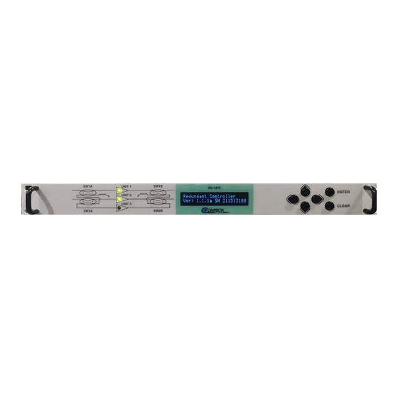
Comtech EF Data RC-1170 Manuals
Manuals and User Guides for Comtech EF Data RC-1170. We have
1
Comtech EF Data RC-1170 manual available for free PDF download: Installation And Operation Manual
Comtech EF Data RC-1170 Installation And Operation Manual (94 pages)
Redundancy Switch Controllers
Brand:
Comtech EF Data
| Category:
Controller
| Size: 5.05 MB
Table of Contents
Table of Contents
3
Preface
11
About this Manual
11
Conventions and References
11
Patents and Trademarks
11
Warnings, Cautions, Notes, and References
12
Examples of Multi-Hazard Notices
12
Recommended Standard Designations
13
Safety and Compliance
13
Electrical Safety and Compliance
13
Class I Pluggable Equipment Type A-Protective Earthing
13
Galvanic Isolator Use
13
Restricted Access Location
14
Electrical Installation
14
Operating Environment
14
European Union Radio Equipment and Telecommunications Terminal Equipment (R&TTE) Directive (1999/5/EC) and en 301 489-1
15
European Union Electromagnetic Compatibility (EMC) Directive (2004/108/EC)
15
European Union Low Voltage Directive (LVD) (2014/35/EC)
16
European Union Rohs Directive (2011/65/EU)
16
European Union Radio Equipment Directive (2014/53/EC)
16
CE Mark
16
Product Support
17
Comtech EF Data Headquarters
17
Warranty Policy
17
Limitations of Warranty
17
Exclusive Remedies
18
Chapter 1. Introduction
19
Figure 1-1. RC-1170 (1:1)
19
Figure 1-2. RC-1270 (1:2)
19
Overview
20
Figure 1-3. Indoor Controller/Outdoor 1:2 LNA Switch System
21
Figure 1-4. Indoor Controller/Outdoor 1:1 LNA Switch System
21
Figure 1-5. Indoor Controller/Outdoor 1:2 LNB Switch System
22
Figure 1-6. Indoor Controller/Outdoor 1:1 LNB Switch System
22
Specifications
23
1.2.1 Front Panel Controls
23
1.2.2 Rear Panel Controls
23
1.2.3 Indicators
24
Chapter 2. Installation and Connectors
25
Unpack and Inspect the Shipment
25
Rack-Mount Installation
26
Figure 2-1. Redundancy Switch Controller Package Content
26
Connectors
27
Power Connection
27
DC Filter Input Module (RC-1170 Only)
28
Table 2-1. DC Input Filter Module Pinouts
28
J1, Control and Bias
29
Table 2-2. 'J1' Controller LNA/LNB Output Connector
29
J3, Eia 232/485
31
Table 2-5. 'J3' EIA-232 Interface Connector Pinout
31
Table 2-4. 'J3' 4-Wire EIA-485 Interface Connector Pinout
31
J4, '10/100 ETHERNET' Management Utility Port
32
Table 2-6. 'J4 Unit Comm' 10/100 Ethernet M&C Interface Connector Pinout
32
Bias Select Switch
33
Current Cal Switch
33
Table 2-3. 'J3' 2-Wire EIA-485 Interface Connector Pinout
31
Table 2-7. Controller to Unit Ethernet Connection (Optional)
33
Chapter 3. Front Panel Operation
35
Overview
35
Figure 3-1. RC-1170 Front Panel
35
Figure 3-2. RC-1270 Front Panel
35
Leds
36
Table 3-1. Front Panel Features
36
Keypad
37
Screen Saver
37
Vacuum Fluorescent Display (VFD)
37
Front Panel Menus
38
Select: Menu
38
Table 3-2. Select Menu Description
38
Select: Config Menu
39
Select: Config: Remote Control Menu
39
Select: Config: Unit Menu
39
Table 3-3. Select: Config Menu Description
39
Table 3-4. Select: Config: Remote Menu Description
39
Table 3-5. Select: Config: Unit Menu Description
39
Select: Config: Redundancy Menu
41
Select: Config Mask Menu
41
Select: Monitor Menu
42
Select: Monitor: Unit 1/2/3
42
Select: Status Menu
42
Select: Status: Faults Menu
42
Select: Status: Event Log Menu
43
Select: Status: Temperature
43
Select: Status: Voltage
43
Select: Utility Menu
44
Select: Utility: Date/Time
44
Select: Utility: Display
44
Select: Utility: Firmware (Images)
44
Modes of Operation
46
RC-1170 (Future Feature)
46
Single and Dual Mode (Future)
46
1:1 Configuration Mode
46
Triple Single Mode (Future)
46
1:2 Redundant Mode
47
Calibration
48
Calibration Requirement
48
Calibration Failure
48
Internal Adjustments and Switches
48
Power Supply Voltage
48
Chapter 4. Firmware Updates
49
Overview
49
4.1.1 Important Considerations
49
4.1.2 Firmware Update Procedure Summary
49
Figure 4-1. Upgrade Webpage Example
50
4.1.3 about Firmware Numbers, File Versions, and Formats
51
Download and Extract the Firmware Update Files
51
Chapter 5. Ethernet Interface Operation
53
Overview
53
5.1.1 Prerequisites
53
SNMP Interface
54
5.2.1 Management Information Base (MIB) Files
54
CEFD Root MIB File
54
RC-1170/1270 Redundancy Switch Controller MIB File
54
RC-1170/1270 Redundancy Switch Controller Traps MIB File
54
5.2.2 SNMP Community Strings
55
5.2.3 SNMP Traps
55
Telnet Interface
58
5.3.1 Telnet Remote Control Operation Via Tera Term
58
Figure 5-1. Telnet Interface Example - Windows Command-Line
58
Configure Tera Term for Telnet Remote Control Operation
59
Figure 5-2. Telnet Interface Example - Tera Term
59
Figure 5-3. Configure Tera Term
59
HTTP (Web Server) Interface
60
5.4.1 Enable the HTTP Interface
60
Figure 5-4. Open Windows Command-Line
60
5.4.2 HTTP Interface User Login
61
Figure 5-5. Telnet Login and Remote Command Execution
61
Figure 5-6. RC-1170/1270 Redundancy Switch Controller HTTP Interface 'Splash
62
5.4.3 HTTP Interface Features
63
Menu Tree
63
5.4.4 HTTPS Web Navigation
63
Page Navigation
63
Page Sections
63
Figure 5-7. RC-1170/1270 Redundancy Switch Controller HTTP Interface Menu Tree
63
Action Buttons
64
Drop-Down Lists
64
Text or Data Entry
64
HTTP Interface
65
Home
65
Home | Home
65
Figure 5-8. RC-1170/1270 Redundancy Switch Controller 'Home | Home' Page (50 W Unit Example Shown)
65
Home | Contact
66
Figure 5-9. 'Home | Contact' Page
66
Admin (Administration)
67
Admin | Access
67
Figure 5-10. 'Admin | Access' Page
67
Admin | Time
69
Figure 5-11. 'Admin | Time' Page
69
Admin | SNMP
70
Figure 5-12. 'Admin | SNMP' Page
70
Admin | Upgrade
71
Figure 5-13. 'Admin | Upgrade' Page
71
Config
72
Config | Unit
72
Configuration | Redundancy
73
Configuration | Mask
74
Config | Utility
75
Status
76
Status | Summary
76
Status | Status
77
Status | Events
78
Appendix A. Redundancy Drawings
79
Figure A-1. C-Band LNA 1:1 Redundant System Assembly
79
Figure A-2. C-Band LNA 1:1 Redundant System (Exploded View
80
Figure A-3. C-Band LNB 1:1 Redundant System Assembly
81
Figure A-4. C-Band LNB 1:1 Redundant System (Exploded View
82
Figure A-5. Ku-Band LNA 1:1 Redundant System Assembly
83
Figure A-6. Ku-Band LNA 1:1 Redundant System (Exploded View
84
Figure A-7. Ku-Band LNB 1:1 Redundant System Assembly
85
Figure A-8. Ku-Band LNB 1:1 Redundant System (Exploded View
86
Figure A-9. C-Band LNA 1:2 Redundant System Assembly
87
Figure A-10. C-Band LNA 1:2 Redundant System (Exploded View
88
Advertisement
Advertisement
Related Products
Comtech EF Data RC-1270
Comtech EF Data Radyne RCS11
Comtech EF Data Radyne RCS20
Comtech EF Data RAP-100
Comtech EF Data Radyne RCU101
Comtech EF Data RADYNE RRS11
Comtech EF Data ROSS
Comtech EF Data Categories
Modem
Switch
Amplifier
Network Router
Media Converter
More Comtech EF Data Manuals
Login
Sign In
OR
Sign in with Facebook
Sign in with Google
Upload manual
Upload from disk
Upload from URL