Sign In
Upload
Manuals
Brands
Comtech EF Data Manuals
Modem
DMD-2050E
Comtech EF Data DMD-2050E Manuals
Manuals and User Guides for Comtech EF Data DMD-2050E. We have
2
Comtech EF Data DMD-2050E manuals available for free PDF download: Installation And Operation Manual
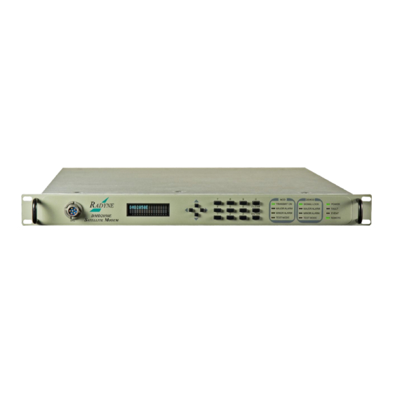
Comtech EF Data DMD-2050E Installation And Operation Manual (379 pages)
Universal Satellite Modem
Brand:
Comtech EF Data
| Category:
Modem
| Size: 14.92 MB
Table of Contents
Terminal Port
7
Installation and Operation Manual
46
Table of Contents
48
About this Manual
62
Cautions and Warnings
62
Patents and Trademarks
62
Preface
62
Related Documents
62
Battery
63
Electrical Safety
63
Fuses
63
Grounding
63
Telecommunications Terminal Equipment Directive
63
EMC (Electromagnetic Compatibility)
64
Environmental
64
Low Voltage Directive (LVD)
64
CE Mark
65
Rohs
65
After Hours and Weekends
66
Comtech EF Data and Radyne Support Contacts
66
On the Web
66
Product Support
66
Return Material Authorization
66
Support Business Hours
66
Exclusive Remedies
67
Limitations of Warranty
67
Warranty Policy
67
Chapter 1. Introduction
68
Overview
68
Figure 1-1. DMD2050E Universal Satellite Modem Front Panel
68
DMD2050E Configurations
69
Features
69
Advanced Forward Error Correction and Modulation
70
Bandwidth Compression
70
Interfaces
71
Remote Control and Monitoring
71
Compatibility
71
Physical Description
71
Dimensional Envelope
72
Configurations and Options
73
Chapter 2. Installation
74
Unpacking and Inspection
74
Installation Safety
75
Installation Considerations
75
Location
76
Airflow
76
Temperature
76
Electrical Power
76
Cables
77
Initial Configuration Check
77
Standard Factory Configuration
77
Modulator Checkout
78
Initial Start up
78
Factory Terminal Settings
78
Chapter 3. Theory of Operation
80
DMD2050E Hardware
80
Figure 3-1. DMD2050E Block Diagram
80
DMD2050E L-Band/If Printed Circuit Card
81
Figure 3-2. if Card Block Diagram
81
DMD2050E Baseband Processing Printed Circuit Card
82
Figure 3-3. DMD2050E Baseband Processing Card Block Diagram
83
Enhanced Interface Printed Circuit Card
84
DMD2050E Functional Block Diagram
84
Front Panel
84
Baseband Processing
84
Tx Baseband Processing
85
Figure 3-4. DMD2050E Universal Satellite Modem Functional Block Diagram
85
Rx Baseband Processing
86
Monitor & Control (M&C) Subsystem
86
Terminal Port
87
Modem Remote Communications (RLLP)
87
Ethernet M&C Port
88
Modem Monitor Status
88
Internal Clock
89
Loopback Features (Terrestrial & IF)
89
Figure 3-5. Loopback Functional Block Diagram
90
Figure 3-6. Loopback Functional Block Diagram
91
DMD2050E Clocking Options
92
Clock Selection
92
Figure 3-7. Loopback Functional Block Diagram
92
TX Clock Options
93
Figure 3-8. Clocking and Polarity Diagram
93
SCTE: Serial Clock Transmit External
94
SCT: Serial Clock Transmit
94
RX Buffer Clock Options
95
RX SAT Clock
95
SCTE: Serial Clock Transmit External
95
SCT: Serial Clock Transmit
96
EXT CLK/EXT BNC: External Clock, J16
96
EXT IDI: Insert Data in
96
EXT REF: External Reference, Top BNC Port, J10
96
Transmit Timing Options
97
MIL-188-114A, RS-422 (TX Clock Source - SCT or SCTE)
97
Interface
97
HSSI Interface
97
Ethernet Data Interface (Optional)
98
Receive Timing Options
98
Loop Timing
98
Transmit (MIL-188-114A, RS-422)
98
Interface or Asymmetrical Data Rates
98
Receive
98
Ebem Framing Unit
99
DMD2050E Information Throughput Adpatation (ITA)
99
Embedded Channel
99
STANAG Turbo Coding
99
Fips TRANSEC Module
100
Traffic Encryption and Decryption Keys and Key Generation
100
Key Agreement
100
Figure 3-9. Traffic Encryption Key Negotiation
101
Figure 3-10. Traffic Decryption Key Negotiation
102
Key Agreement Algorithm
103
Key Derivation
103
Accessing Encryption/Decryption Features
103
Enabling Encryption from the Front Panel
103
Figure 3-11. TRANSEC Secure Web Browser Configuration Page
104
Doubletalk Carrier-In-Carrier Option
105
Figure 3-12. DMD2050E Handheld Key Loader
105
What Is Doubletalk Carrier-In-Carrier
106
Application Requirements
106
Operational Guidelines
108
Figure 3-13. Conceptual Block Diagram
108
System Functionality and Operational Considerations
109
Figure 3-14. Conventional FDMA Link
109
Figure 3-15. same Link Using DMD2050E and Doubletalk Carrier-In-Carrier
110
Table 3-1. Spectral Efficiency Using Doubletalk Carrier-In-Carrier
111
Figure 3-16. Duplex Link Optimization
111
Doubletalk Carrier-In-Carrier Cancellation Process
112
Figure 3-17. Doubletalk Carrier-In-Carrier Signals
113
Figure 3-18. Carrier-In-Carrier Signal Processing Block Diagram
113
Margin Requirements
114
Carrier-In-Carrier Latency
114
Carrier-In-Carrier and Adaptive Coding and Modulation
114
Carrier-In-Carrier Link Design
114
Symmetric Data Rate Link
115
Asymmetric Data Rate Link
118
Power Limited Links
120
Carrier-In-Carrier Commissioning and Deployment
121
Validating Carrier-In-Carrier Performance
123
Operational References
124
Carrier-In-Carrier Link Budget Calculation
124
Estimating PSD Ratio
125
Estimating PSD Ratio from LST
125
Estimating PSD Ratio from Satmaster
126
Estimating PSD Ratio Using Spectrum Analyzer
126
Doubletalk Carrier-In-Carrier Specifications
127
Glossary
128
Carrier-In-Carrier Summary
128
TPC and Low Density Parity Check (LDPC) Coding
130
LDPC Versus TPC
131
Table 3-2. Available TPC and LDPC Modes
132
Figure 3-19. TPC & LDPC Modes Performance (Relative to Shannon Limit)
132
Table 3-3. Comparison of All Comtech EF Data TPC and LDPC Modes
134
TPC and LDPC Summary
135
Reed-Solomon Codec
135
Reed-Solomon Operation in the DMD2050E
135
Figure 3-20. Reed-Solomon Encoder Functional Block Diagram
135
Figure 3-21. Reed-Solomon Decoder Functional Block Diagram
135
Reed-Solomon Code Rate
136
Interleaving
136
DMD2050E Automatic Uplink Power Control (AUPC Operation)
137
Asynchronous Overhead Operation (Async Port / ES-ES Communications)
137
Table 3-4. Reed-Solomon Codes
137
Table 3-5. Baud Rate Examples
138
Standard IBS Mode
139
Asynchronous Multiplexer Mode
140
ESC Backward Alarms
140
To Disable the ESC Backward Alarms
141
Satellite Control Channel (SCC)
141
SCC Framing Structure
141
Figure 3-22. 1 to 3 Control Ratio
142
Figure 3-23. 1 to 1 Control Ratio
142
Aggregate Data Rate
143
Overhead Rate Comparison
144
Actual Overhead Rate Calculation
145
Scc Overhead Channel Setup
146
Locating the DMD2050E ID Code Operational Procedure
148
Chapter 4. User Interfaces
150
User Interfaces
150
Front Panel Interface
150
VFD - Vacuum Fluorescent Display
151
Arrow Keys
151
Numeric Keys
151
Table 4-1. Front Panel Functions
151
Table 4-2. Front Panel Key Functions
151
LED Lights
152
Table 4-3. Front Panel LED Lights
152
Parameter Setup
153
Select a Parameter
153
Enter and Save a New Parameter
153
Change a New Parameter before Saving
153
Front Panel Main Menus
153
Figure 4-2. Enter New Parameters
153
MODULATOR Main Menu and Parameters
154
NETWORK SPEC (Menu)
154
Strap Code
155
IF (Menu)
155
DATA (Menu)
155
EBEM NETWORK SPEC Parameters
157
SCC FRAMING Parameters
157
REED-SOLOMON (Menu)
158
AUPC (Menu)
158
LOCAL AUPC (Menu)
159
REMOTE AUPC (Menu)
162
ITA (Menu)
162
DEMODULATOR Main Menu and Parameters
163
NETWORK SPEC (Menu)
163
Strap Code
164
IF (Menu)
164
DATA (Menu)
165
REED-SOLOMON (Menu)
166
CNC (Menu)
167
ITA (Menu)
167
INTERFACE Main Menu and Parameters
168
TX SETUP (Menu)
168
DROP & INSERT (Menu)
170
TX ASYNC MODE (Menu)
170
RX SETUP (Menu)
171
DROP & INSERT (Menu)
172
RX ASYNC MODE (Menu)
172
GENERAL (Menu)
173
MONITOR Main Menu and Parameters
173
LINK STATUS (Menu)
174
VOLTAGES (Menu)
176
Cnc (Menu)
176
ITA (Menu)
176
ALARMS Main Menu and Parameters
177
SYSTEM Main Menu and Parameters
177
FRONT PANEL (Menu)
177
Remote Control
177
TERMINAL (Menu)
178
REMOTE PORT (Menu)
178
TCP/IP (Menu)
178
SNMP (Menu)
180
FTP (Menu)
181
WEB (Menu)
181
TRANSEC (Menu)
182
HW/FW CONFIG (Menu)
182
MAIN BOARD (Menu)
183
FEATURES (Menu)
184
UPGRADE LIST (Menu)
184
TEST Main Menu and Parameters
185
Terminal Mode Control
187
Terminal Mode Screens
187
Terminal Mode Operations
187
Setup for Terminal Mode
188
Chapter 5. External Connections
190
Figure 5-1. DMD2050E Universal Satellite Modem Front Panel
190
Figure 5-2. DMD2050E Rear Panel
190
Figure 5-3. DMD2050E Rear Panel Configurations
190
Power Connectors, Ground and Switches
191
Ground Connector
191
Power Switch
191
Front Panel Connections
192
Key Loader Interface
192
Table 5-1. Pinouts for SKL Key Loader Interface (RS-232) 6-Pin Female GC283 Connector
192
Figure 4-1. Front Panel
192
Rear Panel Connectors
193
HSSI / Ethernet Connectors
193
Ext Ref (J10)
194
Alarm (J15)
195
IBS Network Alarms Configuration
196
Closed Net Alarms Configuration
196
RTS Carrier Alarms Configuration
196
Ext Clk (J16)
196
Async (J17)
197
ANT. HANDOVER (J18) (Future Option)
197
Mil-188-114A (J19)
198
Table 5-6. Pinouts for J20 REMOTE Port (RS-485 or RS-232) 9-Pin Female D Connector
199
Monitor and Control Connectors J20, J21
199
Chapter 6. Maintenance and Troubleshooting
200
Periodic Maintenance
200
Battery Replacement
200
Clock Adjustment
200
Fuse Replacement
200
Troubleshooting
201
Basic Troubleshooting Procedures
201
Troubleshooting Symptoms and Causes
201
Symptom: the Modem Does Not Acquire the Incoming Carrier
201
Symptom: the ASYNC Port Is Not Configured Correctly
201
Alarms
202
Major Transmit Alarms
202
Major Rx Alarms
202
Minor Tx Alarms
203
Minor Rx Alarms
204
Drop and Insert Alarms
205
Common Major Alarms
205
Alarm Masks
207
Active Alarms
207
Major Alarms
207
Minor Alarms
207
Common Equipment Alarms
208
Latched Alarms
208
Backward Alarms
210
IBS Alarms and Actions
211
Table 6-1. IBS Fault Conditions and Actions (Includes Drop and Insert)
211
Figure 6-1. IBS Alarms
211
Chapter 7. Technical Specifications
212
Modulator
212
Demodulator
213
Plesiochronous Buffer
214
Monitor and Control
214
Terrestrial Interfaces
215
Ibs/Synchronous Interface (Standard)
215
High-Speed Serial Interface (HSSI) & Gigi Ethernet Data Interface
215
Key Loader Interface
215
Environmental
215
Physical
215
Data Rate Limits
216
Non-DVB
216
Dvb
218
BER Specifications
220
BER Performance (Viterbi)
220
Figure 7-1. DMD2050E B/O/QPSK BER Performance (Viterbi)
220
BER Performance (Sequential)
221
Figure 7-2. DMD2050E B/O/QPSK BER Performance (Sequential)
221
BER Performance (Viterbi with Reed-Solomon)
222
Figure 7-3. DMD2050E B/O/QPSK BER Performance (Viterbi with Reed-Solomon)
222
BER Performance (Turbo)
223
Figure 7-4. DMD2050E B/O/QPSK BER Performance (Turbo)
223
BER Performance (8PSK Trellis)
224
Figure 7-5. DMD2050E 8PSK BER Performance (Trellis)
224
BER Performance (8PSK Turbo)
225
Figure 7-6. DMD2050E 8PSK BER Performance (Turbo)
225
BER Performance (16QAM Viterbi)
226
Figure 7-7. DMD2050E 16QAM BER Performance (Viterbi)
226
BER Performance (16QAM Viterbi with Reed-Solomon)
227
Figure 7-8. DMD2050E 16QAM BER Performance (Viterbi with Reed-Solomon)
227
BER Performance (16QAM Turbo)
228
Figure 7-9. DMD2050E 16QAM BER Performance (Turbo)
228
BER Performance (OQPSK Turbo)
229
Figure 7-10. DMD2050E OQPSK BER Performance (Turbo)
229
BER Performance (BPSK Turbo)
230
Figure 7-11. DMD2050E BPSK BER Performance (Turbo)
230
BER Performance (8PSK Turbo)
231
BER Performance (16QAM Turbo)
232
Figure 7-13. DMD2050E 16QAM BER Performance (Turbo)
232
B/O/QPSK BER Performance (LDPC)
233
Figure 7-14. DMD2050E B/O/QPSK BER Performance (LDPC)
233
8PSK / 8QAM BER Performance (LDPC)
234
Figure 7-15. DMD2050E 8PSK / 8QAM BER Performance (LDPC)
234
16QAM BER Performance (LDPC)
235
Figure 7-16. DMD2050E 16QAM BER Performance (LDPC)
235
BER Performance B/O/QPSK (MILSTD 188-165B or STANAG) Turbo
236
Figure 7-17. DMD2050E BER Performance B/O/QPSK (MILSTD 188-165B or STANAG) Turbo
236
BER Performance 8-PSK (MILSTD 188-165B or STANAG) Turbo
237
Figure 7-18. DMD2050E BER Performance 8-PSK (MILSTD 188-165B or STANAG) Turbo
237
BER Performance 16APSK (MILSTD 188-165B or STANAG) Turbo
238
AGC Output Voltage
245
Appendix A. Product Options
246
Hardware Options
246
Custom Options
246
Appendix B. Front Panel Upgrades and Demonstration Mode
248
Introduction
248
Required Equipment
248
Procedures
248
B.1 Introduction
248
Record the Features and Options
249
Record the Unit ID
250
Order the Demonstration or the Upgrade
250
Install the Code
251
Demonstration Mode Considerations
252
Cancel the Demonstration Mode
253
Appendix C. Carrier Control
254
Carrier Control and Alarms
254
Carrier States and Changes to Programming
254
Carrier States
255
Carrier off
255
Carrier on
255
Carrier AUTO
255
C.3 Carrier States
255
Carrier VSAT
256
Carrier Rts
256
C.3.4 Carrier VSAT
256
Appendix D. Web Interface Setup Guide
258
Introduction
258
Setup
258
TCP-IP Menus
258
D.1 Introduction
258
IP Address
259
Web Interface Security
259
Default User Accounts
259
D.2.2 IP Address
259
User Account Data
260
User Account Setup
260
Edit the User ID
261
Edit the Access Group
261
Edit the Authentication Password
261
Reset a User Account
262
Confirmation
262
Equipment Website
263
Figure D-1. WEB Browser Equipment Introduction Page
263
D.4 Equipment Website
263
Log in to the Equipment Website
264
Figure D-2. Login Window
264
D.5 Web Page Appearance
265
Configure Web Browsers for the Radyne WEB Interface
266
Configure Internet Explorer 9 for the Radyne WEB Interface
266
Configure Firefox for the Radyne WEB Interface
266
Change the Encoding
267
Install the Internet Explorer Tab V2 Add-On
268
Configure Chrome for the Radyne WEB Browser
269
Change the Encoding
270
Install the Internet Explorer Tab for Chrome
271
Configure Safari for the Radyne WEB Browser
272
Empty the Browser Cache
272
Reset the Ethernet M&C Port
273
Re-Enter the Modem IP Address
273
Change the Encoding
275
Configure Maxthon for the Radyne WEB Browser
276
Change the Browser Mode
277
Change the Encoding
278
Appendix E. Drop and Insert (Standard and Efficient Options
280
Introduction
280
System Requirements
280
Configuration Examples
281
E.3 Configuration Examples
281
Functional Descriptions
283
Drop Only
283
Insert Only
283
E.4 Functional Descriptions
283
Data Formats
285
Pcm-30C
285
E.4.3 Data Formats
285
Pcm-31C
286
T1-D4/T1-D4-S
286
T1-Esf/T1-Esf-S
286
Systems with Multiple Destinations
286
Drop and Insert Mapping
286
E.4.3.4 Pcm-31C
286
Configuring the Modem for Drop and Insert
289
Data Rate
290
E.5.1 Data Rate
290
Operational Network Specification
291
Terrestrial Framing - Drop Mode/Insert Mode
291
Insert Terrestrial Frame Source
292
D&I Sample Configurations and D&I Clock Setup Options
292
D&I Clock Setup Examples
296
D&I Maps and Map Editing
298
Table E-1. D&I Multiplexer Map Locations Used
298
Table E-2. D&I ROM Maps
299
Efficient Drop and Insert Introduction
302
Prerequisite
303
E.8 Prerequisite
303
Efficient Drop and Insert Mode
304
Calculating the Required Satellite Bandwidth
305
Calculating the Basic Efficient D&I Rate
305
Calculating the Efficient D&I Rate with E1 Signaling
305
Calculating the Efficient D&I Rate with Enhanced Asynchronous Overhead
306
Advertisement
Comtech EF Data DMD-2050E Installation And Operation Manual (342 pages)
Universal Satellite Modem
Brand:
Comtech EF Data
| Category:
Modem
| Size: 10.89 MB
Table of Contents
Installation and Operation Manual
1
Terminal Port
7
Table of Contents
11
Preface
25
About this Manual
25
Cautions and Warnings
25
Patents and Trademarks
25
Related Documents
25
Electrical Safety
26
Battery
26
Grounding
26
Fuses
26
Telecommunications Terminal Equipment Directive
26
Environmental
27
Low Voltage Directive (LVD)
27
EMC (Electromagnetic Compatibility)
27
CE Mark
28
Rohs
28
Product Support
29
On the Web
29
Return Material Authorization
29
Support Business Hours
29
After Hours and Weekends
29
Comtech EF Data and Radyne Support Contacts
29
Warranty Policy
30
Limitations of Warranty
30
Exclusive Remedies
30
Chapter 1. Introduction
31
Overview
31
Figure 1-1. DMD2050E Universal Satellite Modem Front Panel
31
DMD2050E Configurations
32
Features
32
Advanced Forward Error Correction and Modulation
33
Bandwidth Compression
33
Interfaces
34
Remote Control and Monitoring
34
Compatibility
34
Physical Description
34
Dimensional Envelope
35
Configurations and Options
36
Chapter 2. Installation
37
Unpacking and Inspection
37
Installation Safety
38
Installation Considerations
38
Location
39
Airflow
39
Temperature
39
Electrical Power
39
Cables
40
Initial Configuration Check
40
Standard Factory Configuration
40
Modulator Checkout
41
Initial Start up
41
Factory Terminal Settings
41
Chapter 3. Theory of Operation
43
DMD2050E Hardware
43
Figure 3-1. DMD2050E Block Diagram
43
DMD2050E L-Band/If Printed Circuit Card
44
Figure 3-2. if Card Block Diagram
44
DMD2050E Baseband Processing Printed Circuit Card
45
Figure 3-3. DMD2050E Baseband Processing Card Block Diagram
46
Enhanced Interface Printed Circuit Card
47
DMD2050E Functional Block Diagram
47
Front Panel
47
Baseband Processing
47
Tx Baseband Processing
48
Figure 3-4. DMD2050E Universal Satellite Modem Functional Block Diagram
48
Rx Baseband Processing
49
Monitor & Control (M&C) Subsystem
49
Terminal Port
50
Modem Remote Communications (RLLP)
50
Ethernet M&C Port
51
Modem Monitor Status
51
Internal Clock
52
Loopback Features (Terrestrial & IF)
52
Figure 3-5. Loopback Functional Block Diagram
53
Figure 3-6. Loopback Functional Block Diagram
54
DMD2050E Clocking Options
55
Clock Selection
55
Figure 3-7. Loopback Functional Block Diagram
55
TX Clock Options
56
Figure 3-8. Clocking and Polarity Diagram
56
SCT: Serial Clock Transmit
57
SCTE: Serial Clock Transmit External
57
RX Buffer Clock Options
58
RX SAT Clock
58
SCTE: Serial Clock Transmit External
58
SCT: Serial Clock Transmit
59
EXT CLK/EXT BNC: External Clock, J16
59
EXT IDI: Insert Data in
59
EXT REF: External Reference, Top BNC Port, J10
59
Transmit Timing Options
60
MIL-188-114A, RS-422 (TX Clock Source - SCT or SCTE)
60
Interface
60
HSSI Interface
60
Ethernet Data Interface (Optional)
61
Receive Timing Options
61
Loop Timing
61
Transmit (MIL-188-114A, RS-422)
61
Interface or Asymmetrical Data Rates
61
Receive
61
Ebem Framing Unit
62
DMD2050E Information Throughput Adpatation (ITA)
62
Embedded Channel
62
STANAG Turbo Coding
62
Fips TRANSEC Module
63
Traffic Encryption and Decryption Keys and Key Generation
63
Key Agreement
63
Figure 3-9. Traffic Encryption Key Negotiation
64
Figure 3-10. Traffic Decryption Key Negotiation
65
Key Agreement Algorithm
66
Key Derivation
66
Accessing Encryption/Decryption Features
66
Enabling Encryption from the Front Panel
66
Figure 3-11. TRANSEC Secure Web Browser Configuration Page
67
Doubletalk Carrier-In-Carrier Option
68
Figure 3-12. DMD2050E Handheld Key Loader
68
What Is Doubletalk Carrier-In-Carrier
69
Application Requirements
69
Operational Guidelines
71
Figure 3-13. Conceptual Block Diagram
71
System Functionality and Operational Considerations
72
Figure 3-14. Conventional FDMA Link
72
Figure 3-15. same Link Using DMD2050E and Doubletalk Carrier-In-Carrier
73
Table 3-1. Spectral Efficiency Using Doubletalk Carrier-In-Carrier
74
Figure 3-16. Duplex Link Optimization
74
Doubletalk Carrier-In-Carrier Cancellation Process
75
Figure 3-17. Doubletalk Carrier-In-Carrier Signals
76
Figure 3-18. Carrier-In-Carrier Signal Processing Block Diagram
76
Margin Requirements
77
Carrier-In-Carrier Latency
77
Carrier-In-Carrier and Adaptive Coding and Modulation
77
Carrier-In-Carrier Link Design
77
Symmetric Data Rate Link
78
Asymmetric Data Rate Link
81
Power Limited Links
83
Carrier-In-Carrier Commissioning and Deployment
84
Validating Carrier-In-Carrier Performance
86
Operational References
87
Carrier-In-Carrier Link Budget Calculation
87
Estimating PSD Ratio
88
Estimating PSD Ratio from LST
88
Estimating PSD Ratio from Satmaster
89
Estimating PSD Ratio Using Spectrum Analyzer
89
Doubletalk Carrier-In-Carrier Specifications
90
Carrier-In-Carrier Summary
91
Glossary
91
TPC and Low Density Parity Check (LDPC) Coding
93
LDPC Versus TPC
94
Table 3-2. Available TPC and LDPC Modes
95
Figure 3-19. TPC & LDPC Modes Performance (Relative to Shannon Limit)
95
Table 3-3. Comparison of All Comtech EF Data TPC and LDPC Modes
97
TPC and LDPC Summary
98
Reed-Solomon Codec
98
Reed-Solomon Operation in the DMD2050E
98
Figure 3-20. Reed-Solomon Encoder Functional Block Diagram
98
Figure 3-21. Reed-Solomon Decoder Functional Block Diagram
98
Reed-Solomon Code Rate
99
Interleaving
99
DMD2050E Automatic Uplink Power Control (AUPC Operation)
100
Asynchronous Overhead Operation (Async Port / ES-ES Communications)
100
Table 3-4. Reed-Solomon Codes
100
Table 3-5. Baud Rate Examples
101
Standard IBS Mode
102
Table 3-6. Bits of Overhead Housekeeping Byte 32
102
Asynchronous Multiplexer Mode
103
ESC Backward Alarms
103
To Disable the ESC Backward Alarms
104
Satellite Control Channel (SCC)
104
SCC Framing Structure
104
Figure 3-22. 1 to 3 Control Ratio
105
Figure 3-23. 1 to 1 Control Ratio
105
Aggregate Data Rate
106
Overhead Rate Comparison
107
Actual Overhead Rate Calculation
108
Scc Overhead Channel Setup
109
Locating the DMD2050E ID Code Operational Procedure
111
Chapter 4. User Interfaces
113
User Interfaces
113
Front Panel Interface
113
VFD - Vacuum Fluorescent Display
114
Arrow Keys
114
Numeric Keys
114
Table 4-1. Front Panel Functions
114
Table 4-2. Front Panel Key Functions
114
LED Lights
115
Table 4-3. Front Panel LED Lights
115
Front Panel Main Menus
116
Figure 4-2. Enter New Parameters
116
MODULATOR Main Menu and Parameters
117
NETWORK SPEC (Menu)
117
DATA (Menu)
118
IF (Menu)
118
Strap Code
118
EBEM NETWORK SPEC Parameters
120
SCC FRAMING Parameters
120
AUPC (Menu)
121
REED-SOLOMON (Menu)
121
LOCAL AUPC (Menu)
122
ITA (Menu)
125
REMOTE AUPC (Menu)
125
DEMODULATOR Main Menu and Parameters
126
NETWORK SPEC (Menu)
126
IF (Menu)
127
Strap Code
127
DATA (Menu)
128
REED-SOLOMON (Menu)
129
CNC (Menu)
130
ITA (Menu)
130
INTERFACE Main Menu and Parameters
131
TX SETUP (Menu)
131
DROP & INSERT (Menu)
133
TX ASYNC MODE (Menu)
133
RX SETUP (Menu)
134
DROP & INSERT (Menu)
135
RX ASYNC MODE (Menu)
135
GENERAL (Menu)
136
MONITOR Main Menu and Parameters
136
LINK STATUS (Menu)
137
Cnc (Menu)
139
ITA (Menu)
139
VOLTAGES (Menu)
139
ALARMS Main Menu and Parameters
140
SYSTEM Main Menu and Parameters
140
FRONT PANEL (Menu)
140
Remote Control
140
REMOTE PORT (Menu)
141
TCP/IP (Menu)
141
TERMINAL (Menu)
141
SNMP (Menu)
143
FTP (Menu)
144
WEB (Menu)
144
HW/FW CONFIG (Menu)
145
TRANSEC (Menu)
145
MAIN BOARD (Menu)
146
FEATURES (Menu)
147
UPGRADE LIST (Menu)
147
TEST Main Menu and Parameters
148
Parameter Setup
116
Select a Parameter
116
Enter and Save a New Parameter
116
Change a New Parameter before Saving
116
Terminal Mode Control
150
Terminal Mode Screens
150
Terminal Mode Operations
150
Setup for Terminal Mode
151
Chapter 5. External Connections
153
Figure 5-1. DMD2050E Universal Satellite Modem Front Panel
153
Figure 5-2. DMD2050E Rear Panel
153
Figure 5-3. DMD2050E Rear Panel Configurations
153
Power Connectors, Ground and Switches
154
Ground Connector
154
Power Switch
154
Front Panel Connections
155
Key Loader Interface
155
Table 5-1. Pinouts for SKL Key Loader Interface (RS-232) 6-Pin Female GC283 Connector
155
Figure 4-1. Front Panel
155
Rear Panel Connectors
156
HSSI / Ethernet Connectors
156
Ext Ref (J10)
157
IF Connectors (Transmit and Receive) J11, J12, J13, J14
157
Alarm (J15)
158
IBS Network Alarms Configuration
159
Closed Net Alarms Configuration
159
RTS Carrier Alarms Configuration
159
Ext Clk (J16)
159
Async (J17)
160
ANT. HANDOVER (J18) (Future Option)
160
Mil-188-114A (J19)
161
Table 5-6. Pinouts for J20 REMOTE Port (RS-485 or RS-232) 9-Pin Female D Connector
162
Monitor and Control Connectors J20, J21
162
Chapter 6. Maintenance and Troubleshooting
163
Periodic Maintenance
163
Battery Replacement
163
Clock Adjustment
163
Fuse Replacement
163
Troubleshooting
164
Basic Troubleshooting Procedures
164
Troubleshooting Symptoms and Causes
164
Symptom: the Modem Does Not Acquire the Incoming Carrier
164
Symptom: the ASYNC Port Is Not Configured Correctly
164
Alarms
165
Major Transmit Alarms
165
Major Rx Alarms
165
Minor Tx Alarms
166
Minor Rx Alarms
167
Drop and Insert Alarms
168
Common Major Alarms
168
Alarm Masks
170
Active Alarms
170
Major Alarms
170
Minor Alarms
170
Common Equipment Alarms
171
Latched Alarms
171
Backward Alarms
173
IBS Alarms and Actions
174
Table 6-1. IBS Fault Conditions and Actions (Includes Drop and Insert)
174
Figure 6-1. IBS Alarms
174
Chapter 7. Technical Specifications
175
Modulator
175
Demodulator
176
Plesiochronous Buffer
177
Monitor and Control
177
Terrestrial Interfaces
178
Ibs/Synchronous Interface (Standard)
178
High-Speed Serial Interface (HSSI) & Gigi Ethernet Data Interface
178
Key Loader Interface
178
Environmental
178
Physical
178
Data Rate Limits
179
Non-DVB
179
Dvb
181
BER Specifications
183
BER Performance (Viterbi)
183
Figure 7-1. DMD2050E B/O/QPSK BER Performance (Viterbi)
183
BER Performance (Sequential)
184
Figure 7-2. DMD2050E B/O/QPSK BER Performance (Sequential)
184
BER Performance (Viterbi with Reed-Solomon)
185
Figure 7-3. DMD2050E B/O/QPSK BER Performance (Viterbi with Reed-Solomon)
185
BER Performance (Turbo)
186
Figure 7-4. DMD2050E B/O/QPSK BER Performance (Turbo)
186
BER Performance (8PSK Trellis)
187
Figure 7-5. DMD2050E 8PSK BER Performance (Trellis)
187
BER Performance (8PSK Turbo)
188
Figure 7-6. DMD2050E 8PSK BER Performance (Turbo)
188
BER Performance (16QAM Viterbi)
189
Figure 7-7. DMD2050E 16QAM BER Performance (Viterbi)
189
BER Performance (16QAM Viterbi with Reed-Solomon)
190
Figure 7-8. DMD2050E 16QAM BER Performance (Viterbi with Reed-Solomon)
190
BER Performance (16QAM Turbo)
191
Figure 7-9. DMD2050E 16QAM BER Performance (Turbo)
191
BER Performance (OQPSK Turbo)
192
Figure 7-10. DMD2050E OQPSK BER Performance (Turbo)
192
BER Performance (BPSK Turbo)
193
Figure 7-11. DMD2050E BPSK BER Performance (Turbo)
193
BER Performance (8PSK Turbo)
194
BER Performance (16QAM Turbo)
195
Figure 7-13. DMD2050E 16QAM BER Performance (Turbo)
195
B/O/QPSK BER Performance (LDPC)
196
Figure 7-14. DMD2050E B/O/QPSK BER Performance (LDPC)
196
8PSK / 8QAM BER Performance (LDPC)
197
Figure 7-15. DMD2050E 8PSK / 8QAM BER Performance (LDPC)
197
16QAM BER Performance (LDPC)
198
Figure 7-16. DMD2050E 16QAM BER Performance (LDPC)
198
BER Performance B/O/QPSK (MILSTD 188-165B or STANAG) Turbo
199
Figure 7-17. DMD2050E BER Performance B/O/QPSK (MILSTD 188-165B or STANAG) Turbo
199
BER Performance 8-PSK (MILSTD 188-165B or STANAG) Turbo
200
Figure 7-18. DMD2050E BER Performance 8-PSK (MILSTD 188-165B or STANAG) Turbo
200
BER Performance 16APSK (MILSTD 188-165B or STANAG) Turbo
201
AGC Output Voltage
208
Appendix A. Product Options
209
Hardware Options
209
Custom Options
209
A.1 Hardware Options
209
A.2 Custom Options
209
Appendix B. Front Panel Upgrades and Demonstration Mode
211
Introduction
211
Required Equipment
211
Procedures
211
B.1 Introduction
211
B.2 Required Equipment
211
B.3 Procedures
211
Record the Features and Options
212
Order the Demonstration or the Upgrade
213
Record the Unit ID
213
Install the Code
214
Demonstration Mode Considerations
215
Cancel the Demonstration Mode
216
Appendix C. Carrier Control
217
Carrier Control and Alarms
217
Carrier States and Changes to Programming
217
Carrier States
218
Carrier off
218
Carrier on
218
Carrier AUTO
218
C.3 Carrier States
218
C.3.1 Carrier off
218
C.3.2 Carrier on
218
C.3.3 Carrier AUTO
218
Carrier VSAT
219
Carrier Rts
219
C.3.4 Carrier VSAT
219
C.3.5 Carrier Rts
219
Appendix D. Web Interface Setup Guide
221
Introduction
221
Setup
221
TCP-IP Menus
221
D.1 Introduction
221
D.2 Setup
221
D.2.1 TCP-IP Menus
221
IP Address
222
Web Interface Security
222
Default User Accounts
222
D.2.2 IP Address
222
D.3 Web Interface Security
222
D.3.1 Default User Accounts
222
User Account Data
223
User Account Setup
223
Edit the User ID
224
Edit the Access Group
224
Edit the Authentication Password
224
Reset a User Account
225
Confirmation
225
D.3 Confirmation
225
Equipment Website
226
D.4 Equipment Website
226
Figure D-1. WEB Browser Equipment Introduction Page
226
Figure D-2. Login Window
227
Log in to the Equipment Website
227
D.5 Web Page Appearance
228
Configure Web Browsers for the Radyne WEB Interface
229
Configure Internet Explorer 9 for the Radyne WEB Interface
229
Configure Firefox for the Radyne WEB Interface
229
Change the Encoding
230
Install the Internet Explorer Tab V2 Add-On
231
Configure Chrome for the Radyne WEB Browser
232
Change the Encoding
233
Install the Internet Explorer Tab for Chrome
234
Configure Safari for the Radyne WEB Browser
235
Empty the Browser Cache
235
Reset the Ethernet M&C Port
236
Re-Enter the Modem IP Address
236
Change the Encoding
238
Configure Maxthon for the Radyne WEB Browser
239
Change the Browser Mode
240
Change the Encoding
241
Appendix E. Drop and Insert (Standard and Efficient Options
243
Introduction
243
System Requirements
243
E.1 Introduction
243
E.2 System Requirements
243
Configuration Examples
244
E.3 Configuration Examples
244
Functional Descriptions
246
Drop Only
246
Insert Only
246
E.4 Functional Descriptions
246
E.4.1 Drop Only
246
E.4.2 Insert Only
246
Data Formats
248
Pcm-30C
248
E.4.3 Data Formats
248
E.4.3.1 Pcm-30
248
E.4.3.2 Pcm-30C
248
Pcm-31C
249
T1-D4/T1-D4-S
249
T1-Esf/T1-Esf-S
249
E.4.3.4 Pcm-31C
249
E.4.3.5 T1-D4/T1-D4-S
249
E.4.3.6 T1-Esf/T1-Esf-S
249
Systems with Multiple Destinations
249
Drop and Insert Mapping
249
Configuring the Modem for Drop and Insert
252
Data Rate
253
E.5.1 Data Rate
253
Operational Network Specification
254
Terrestrial Framing - Drop Mode/Insert Mode
254
Insert Terrestrial Frame Source
255
D&I Sample Configurations and D&I Clock Setup Options
255
D&I Clock Setup Examples
259
D&I Maps and Map Editing
261
Table E-1. D&I Multiplexer Map Locations Used
261
Table E-2. D&I ROM Maps
262
Advertisement
Related Products
Comtech EF Data DMD50
Comtech EF Data DMD1050TS
Comtech EF Data Radyne DM240XR
Comtech EF Data Radyne DMD1050
Comtech EF Data DT-4500 Series
Comtech EF Data DT-4503/D
Comtech EF Data DT-4510/D
Comtech EF Data DT-4511
Comtech EF Data DT-4512
Comtech EF Data DT-4512/E
Comtech EF Data Categories
Modem
Switch
Amplifier
Network Router
Media Converter
More Comtech EF Data Manuals
Login
Sign In
OR
Sign in with Facebook
Sign in with Google
Upload manual
Upload from disk
Upload from URL