Sign In
Upload
Manuals
Brands
Carrier Manuals
Refrigerator
SUPRA 950Mt
Carrier SUPRA 950Mt Manuals
Manuals and User Guides for Carrier SUPRA 950Mt. We have
3
Carrier SUPRA 950Mt manuals available for free PDF download: Operation & Service Manual, Operation And Service Manual, Operator's Manual
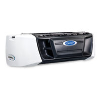
Carrier SUPRA 950Mt Operation & Service Manual (116 pages)
Truck Refrigeration Units with Cab Command Controller
Brand:
Carrier
| Category:
Refrigerator
| Size: 7.74 MB
Table of Contents
Table of Contents
5
Paragraph Number
11
Safety Precautions
11
First Aid
11
Operating Precautions
11
Maintenance Precautions
12
Auto-Start
12
Engine Coolant
12
Refrigerants
12
Battery
12
Specific Warning, Caution, and Notice Statements
13
1.10 Safety Decals
16
Table Number
19
Unit Description
19
Introduction
19
Table 2-1 Additional Support Manuals
19
Table 2-2 Model Chart
19
Table 2-3 Evaporator Model Chart
19
Figure 2.1 Supra 950MT Model - Top View/Cab Command
20
Figure Number
20
Figure 2.2 Supra 950MT Model - Curbside View
21
Figure 2.3 Supra 950MT Model - Roadside View
21
Figure 2.4 Evaporator (MTS 1100 Illustrated)
22
Figure 2.5 Electrical Box
23
Figure 2.6 Control Relay Board View
24
Figure 2.7 Multi-Temp Sub Panel
24
Table 2-4 Fuse Identification
25
Table 2-5 Relay Identification
25
General Description
26
System
26
Truck Condensing Units
26
Table 2-6 Test Point Identification
26
Multi-Temperature Evaporators
27
Condensing Section
27
Drive Equipment
27
Figure 2.8 Supra 950MT Serial Number Plate
27
Switches and Controls
28
Description of Cab Command Components
28
Keypad
28
Condensing Section Refrigeration System
30
Figure 2.9 70 Amp Alternator
30
Figure 2.10 Cylinder Head - Unloaded
31
Figure 2.11 Cylinder Head - Loaded
32
Remote Evaporator Sections
33
Evaporator Coil
33
Thermal Expansion Valve (TXV)
33
Defrost Termination Temperature Sensor (DTS)
33
Figure 2.12 Accumulator/Subcooler/Heat Exchanger
33
Electric and Electric Hot/Gas Heat
34
Receiver Pressure Valve (RPV)
34
Main Heat Valve (MHV)
34
Remote Evaporator Hot Gas Valve (1HGV and 2HGV)
34
Liquid Solenoid Valve
34
Electric Evaporator Fan Motor
34
System Operating Controls and Components
35
Switches and Controls
35
Water Temperature Sensor (WTS)
35
Lubrication System
36
Table 2-7 Lube Oil Viscosity
36
Compressor Reference Data
37
Refrigeration System Data
37
Electrical Data
37
Torque Values
38
Safety Devices
38
Table 2-8 Safety Devices
38
2.10 Refrigerant Circuit During Heat and Defrost
39
Hot Gas Heating
39
Principle of Induction Heating (Electric Heat)
40
Figure 2.13 Refrigeration Circuit - Cooling
41
Figure 2.14 Refrigeration Circuit - Heating
42
Refrigerant Circuit During Cooling
39
Operation
43
Microprocessor
43
Figure 3.1 Cab Command
43
Introduction
44
Microprocessor Configuration
44
Before Starting the Unit
44
Starting Unit - Engine / Road Operation
45
Starting Unit - Electric / Standby Operation
46
Start / Stop Operation
47
Continuous Run Operation
48
Changing Set Point
49
Manual Defrost
50
3.10 Function Change
51
Table 3-1 Function Parameters
52
3.11 Unit Data / Compartment Menus
53
Compartment Status Menu
54
Compartment Selection Menu
54
Unit Operating Data Parameters
54
Table 3-2 Display for Compartment 1 Turned on
54
Table 3-3 Display for Compartment 2 Turned on
54
Table 3-4 Display for All Compartments on
54
Table 3-5 Display for All Compartments off
54
Table 3-6 Unit Data Codes
55
3.12 Alarm Display and Reset
57
Table 3-7 Alarm Display
57
3.13 Stopping Unit
60
3.14 Remote Panel
60
3.15 Modes of Operation
64
Heat/Cool Mode
64
Defrost Cycle
64
Continuous or Start-Stop Operation
64
Table 3-8 Engine Coolant Temperature Glow Time
65
3.16 Pre Trip Inspection
66
Before Starting Engine
66
Table 3-9 Battery Voltages
66
After Starting Refrigeration Unit
67
3.17 Microprocessor Operation
67
Control Logic and Temperature Control
69
Modes of Operation
69
Introduction
69
Temperature Control Logic
69
Logic
70
Relay Operation
70
Table 4-1 Relay Operation
70
Lead Compartment Decision
71
Pulse Sequence
71
Figure 4.1 Temperature Controller Op Seq (Frozen Range) Controller Set Point below +10°F (-12°C)
71
Figure 4.2 Perishable Continuous Mode - Normal (Non-Lead)
72
Figure 4.3 Perishable Continuous Mode - Normal (Lead)
72
Figure 4.4 Frozen Continuous Mode
73
Service
75
Maintenance Schedule
75
Oil Change Intervals
75
Table 5-1 Service Category Descriptions
76
Servicing Engine-Related Components
77
Cooling System
77
Figure 5.1 Cooling Circuit
77
Changing Lube Oil and Lube Oil Filters
78
Replacing Solenoid
79
Engine Air Cleaner
79
Figure 5.2 Fuel Filter and Fuel Circuit
79
Servicing Fuel Pump
80
Servicing Glow Plugs
80
Testing Flash Relay Circuit
80
Figure 5.3 Electric Fuel Pump
80
Clutch Control
81
Servicing Alternator
81
Servicing and Adjusting V-Belts Warning
82
Belt Tension Gauge
82
Trapezoidal V-Belt
82
Alternator Belt
82
Figure 5.4 Belt Tension Gauge (Part Number 07-00203-00)
82
Figure 5.5 V-Belt Arrangement
82
Table 5-2 Belt Tension
82
Water Pump V-Belt
83
Standby Motor - Compressor V-Belt Diesel Engine - Compressor V-Belt
83
Pumping down the Unit or Removing Refrigerant Charge
83
Figure 5.6 Water Pump Belt - Idler Retaining Nut
83
Pumping down the Unit
84
Removing the Refrigerant Charge
84
Leak Checking the Unit
84
Evacuation and Dehydration
84
General
84
Preparation
84
Procedure for Evacuating and Dehydrating System
85
Charging the Refrigerant System
86
Installing a Complete Charge
86
Checking the Refrigerant Charge
86
Figure 5.7 Dual Vacuum Pump Connections
86
Replacing the Compressor
87
Figure 5.8 Compressor (05G)
87
Compressor Oil Level
88
Checking Oil Level in 05G Compressor
88
Adding Oil with Compressor in System
88
Adding Oil to Service Replacement Compressor
88
Removing Oil from the Compressor
89
5.10 Compressor Unloader Valve
89
Checkout Procedure
89
Solenoid Coil Replacement
89
Replacing Solenoid Valve Internal Parts
89
5.11 Checking and Replacing Filter Drier
90
Checking and Replacing High Pressure Cutout Switches (Hp1 or Hp2)
90
Removing High Pressure Switch
90
Checking High Pressure Switch
90
Figure 5.9 Unloader Solenoid Valve
90
5.13 Replacing Receiver Sight Glass Assembly
91
Figure 5.10 Typical Setup for Testing High Pressure Switch
91
5.14 Coil Cleaning
92
Evaporator Coil
92
Condenser Coil
92
Adjusting the Compressor Pressure Regulating Valve (Cpr)
92
Figure 5.11 Compressor Pressure Regulating Valve
92
5.16 Thermostatic Expansion Valve
93
Setting and Adjusting Superheat
93
Figure 5.12 Thermostatic Expansion Valve
93
Figure 5.13 Thermostatic Expansion Valve Bulb and Thermocouple
93
Replacing Expansion Valve
94
Table 5-3 Optimum Operating Superheat Temperature Refrigerant Pressure and Type
94
5.17 Suction Pressure Transducer
95
Table 5-4 Sensor Resistance (ATS, CDT, RAS, SAS & WTS)
95
Table 5-5 R404A Temperature-Pressure Chart
96
5.18 Microprocessor
97
Table 5-6 Connection Point Voltage Inputs
97
Controller Sensor Checkout
98
Microprocessor Replacement and Configuration Service Guidelines
98
Table 5-7 Microprocessor Configurations
99
Troubleshooting
101
Diesel Engine
101
Engine will Not Start
101
Engine Starts then Stops
101
Starter Motor Malfunction
102
Malfunction in the Engine Starting Circuit
102
Alternator
102
Refrigeration
103
Unit will Not Cool
103
Unit Runs but Has Insufficient Cooling
103
Unit Operates Long or Continuously in Cooling
103
Unit will Not Heat or Has Insufficient Heating
103
Defrost Cycle Malfunction
104
Abnormal Pressure, Cooling
104
Abnormal Pressure, Heating
105
Abnormal Noise
105
Control System Malfunction
105
No Evaporator Air Flow or Restricted Air Flow
105
Expansion Valve Malfunction
106
Hot Gas Valve Malfunction
106
Electrical Schematic Wiring Diagram
107
Introduction
107
Wiring Schematic
107
Index
113
Advertisement
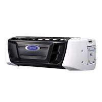
Carrier SUPRA 950Mt Operation And Service Manual (92 pages)
TRUCK REFRIGERATION UNIT
Brand:
Carrier
| Category:
Refrigerator
| Size: 4.53 MB
Table of Contents
Table of Contents
5
Table 2-1 Condensers Model Chart
14
Table 2-2 Evaporators Model Chart
14
Table 2-3 Evaporators Designation
14
Figure 2-1 Supra 750Mt _ / 850Mt
15
Figure 2-2 Supra 950Mt
17
Figure 2-3 Evaporator MTS Model
19
Figure 2-4 Evaporator MTD Model
20
Figure 2-5 Electrical Box
21
Figure 2-6 Control Relay Board View
22
Table 2-4 Safety Devices
26
Figure 2-7 Cab Command
27
Table 2-5 Function Parameters
30
Table 2-7 Unit Data Codes
32
Table 2-8 Alarm Display
33
Figure 2-8 Auto Start Sequence
37
Table 2-10 Battery Voltages
38
Figure 2-9 Main Heat Valves - - no and NC
38
Figure 2-10 Hot Gas & Liquid Suction Valves - - NC
39
Figure 2-11 Accumulator
39
Figure 2-13 Compressor Cylinder Heat Unloader Hot Gas Bypass
40
Figure 2-14 Compressor Cylinder Head Loader Hot Gas Bypass
41
Figure 2-15 50 Amp Alternator and Regulator
42
Figure 2-16 Generator and Connection in Control Box
42
Use of Diagnosis Connection of Control Box (See Figure 2-16)
42
Refrigerant Circuit
44
Heat and Defrost Mode
45
Figure 2-17 Cooling Cycle
46
Operation
48
Operation with Auxiliary Control Panel
50
Control Circuit Operation
52
Table 3-11 Relay Operation - - Microprocessor Controller
53
Relay Operation
55
Figure 3-1 Temperature Controller Operating Sequence (Perishable Range)
56
Figure 3-2 Temperature Controller Operating Sequence "Lead" Evaporator
56
Figure 3-3 Temperature Controller Operating Sequence (Frozen Range)
57
Figure 3-4 Temperature Controller Operating Sequence "Lead" Evaporator
57
Service
58
Description of Service Requirements
59
Servicing Engine Related Components
60
Figure 4-1 Cooling Circuit
60
Figure 4-2 Fuel Filter and Fuel Circuit
61
Changing Lube Oil and Lube Oil Filters
61
Figure 4-3 Speed and Run Control Solenoids
62
Replacing Solenoids (Figure 4-3)
62
Engine Air Cleaner
63
Figure 4-4 Electric Fuel Pump
63
Servicing Glow Plugs
64
Figure 4-6 V-Belt Arrangement
65
Belt Tension Gauge
65
Table 4-1 Belt Tension
65
Figure 4-5 Electronic Belt Tension Meter (Part No. 07-60098--00)
65
Alternator V-Belt
66
Evacuation and Dehydration
67
Figure 4-7 Dual Vacuum Pump Connections
68
Charging the Refrigerant System
68
Figure 4-8 Compressors
69
Replacing the Compressor
69
Figure 4-9 Unloader Solenoid Valve
71
Checking and Replacing Filter-Drier
71
Evaporator Coil
73
Microprocessor
75
Table 4-2 Connection Point Voltage
75
Table 4-3 Microprocessor Configuration
76
Table 4-4 Sensor Resistance (ATS, DTS, CDT, RAS, SAS & WTS)
77
Controller Sensor Checkout
77
Table 4-5 R-404A Temperature-Pressure Chart
78
Suction Pressure Transducer
78
Troubleshooting
79
Engine Starts then Stops
80
Alternator (Automotive Type)
81
Unit Operates Long or Continuously in Cooling
82
Abnormal Noise
83
Figure 4-11 Compressor Pressure Regulating Valve
83
No Evaporator Air Flow Restricted Air Flow
84
Standby Motor Malfunction
85
Extract from Material Safety Data Bulletin
86
Forane R404A
88
Electrical Schematic Wiring Diagram
91
Carrier SUPRA 950Mt Operator's Manual (42 pages)
Truck Refrigeration Units
Brand:
Carrier
| Category:
Refrigerator
| Size: 1.2 MB
Table of Contents
Table of Contents
5
Introduction
7
Unit Identification
8
Safety
9
Pre-Trip Inspection
10
Unit Operation
11
Starting Unit - Engine/Road Operation
12
Starting Unit - Standby Operation
13
Start/Stop Operation
15
Continuous Run Operation
17
Changing Setpoint
18
Manual Defrost
19
Function Change
20
Unit Data
22
Alarm Display & Reset
24
Stopping Unit
27
Product Loading
28
Recommended Transport Temperatures
29
Troubleshooting Tips
30
Control Box Components
32
Multi-Temp Sub Panel
34
Relay Board
35
Unit Maintenance
36
Unit Maintenance Schedule
37
Emergency Road Service
40
Advertisement
Advertisement
Related Products
Carrier SUPRA 850Mt
Carrier SUPRA 750Mt
Carrier 90MA
Carrier Infinity 96 58UVB060F10014
Carrier Infinity 96 58UVB100F10020
Carrier 90GTN
Carrier 9040
Carrier 986TC
Carrier 9HXE
Carrier 900-0280-CAR
Carrier Categories
Air Conditioner
Heat Pump
Furnace
Thermostat
Chiller
More Carrier Manuals
Login
Sign In
OR
Sign in with Facebook
Sign in with Google
Upload manual
Upload from disk
Upload from URL