Sign In
Upload
Manuals
Brands
Carrier Manuals
Air Conditioner
69NT40-561-201
Carrier 69NT40-561-201 Manuals
Manuals and User Guides for Carrier 69NT40-561-201. We have
1
Carrier 69NT40-561-201 manual available for free PDF download: Operation & Service Manual
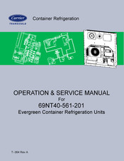
Carrier 69NT40-561-201 Operation & Service Manual (117 pages)
Evergreen Container Refrigeration Units
Brand:
Carrier
| Category:
Air Conditioner
| Size: 4.33 MB
Table of Contents
Table of Contents
9
Figure 2−1 Refrigeration Unit − Front Section
18
Figure 2−2 Evaporator Section
19
Figure 2−3 Compressor Section
20
Figure 2−4 Air−Cooled Condenser Section
21
Figure 2−5 Control Box Section
22
Table 2−1 Safety and Protective Devices
25
Figure 2−6 Refrigeration Circuit Schematic − Standard Operation
27
Figure 2−7 Refrigeration Circuit Schematic − Economized Operation
28
Figure 3−1 Temperature Control System
30
Table 3−1 Keypad Function
31
Figure 3−2 Keypad
31
Figure 3−3 Display Module
32
Figure 3−4 Control Module
32
Figure 3−5 Controller Operation - Perishable Mode
34
Figure 3−6 Perishable Mode Cooling
35
Figure 3−7 Perishable Mode Heating
36
Figure 3−8 Controller Operation - Frozen Mode
37
Figure 3−9 Frozen Mode
38
Figure 3−10 Defrost
38
Table 3−2 Datacorder Configuration Variables
42
Figure 3−11 Standard Configuration Download Report
43
Table 3−3 Datacorder Standard Configurations
44
Table 3−4 Controller Configuration Variables
47
Table 3−5 Controller Function Codes
48
Figure 3−12 Alarm Troubleshooting Sequence
54
Table 3−6 Controller Alarm Indications
55
Table 3−7 Controller Pre-Trip Test Codes
63
Table 3−8 Datacorder Function Code Assignments
69
Table 3−9 Datacorder Pre-Trip Result Records
70
Table 3−10 Datacorder Alarm Indications
71
Figure 4−1 Upper Fresh Air Make up Flow Chart
73
Figure 6−1 Manifold Gauge Set
82
Figure 6−2 R-134A Manifold Gauge/Hose Set
82
Figure 6−3 Service Valve
83
Figure 6−4 Refrigeration System Service Connections
84
Figure 6−5 Compressor Kit
86
Figure 6−6 High Pressure Switch Testing
87
Figure 6−7 Heater Arrangement
90
Figure 6−8 Evaporator Fan Assembly
91
Figure 6−9 Electronic Expansion Valve
92
Figure 6−10 Coil View of Economizer Solenoid Valve (ESV)
93
Figure 6−11 Economizer Expansion Valve
93
Figure 6−12 View of Digital Unloader Valve (DUV) Assembly
94
Table 6−1 Valve Override Control Displays
95
Figure 6−13 Controller Section of the Control Box
96
Table 6−2 Sensor Resistance
99
Table 6−3 Sensor Resistance (CPDS)
100
Figure 6−14 Sensor Types
101
Figure 6−15 Sensor and Cable Splice
101
Figure 6−16 Supply Sensor Positioning
102
Figure 6−17 Return Sensor Positioning
102
Figure 6−18 Evaporator Temperature Sensor Positioning
102
Figure 6−19 Compressor Discharge Temperature Sensor
103
Figure 6−20 Communications Interface Installation
104
Table 6−4 R-134A Temperature - Pressure Chart
105
Table 6−5 Recommended Bolt Torque Values
106
Figure 7−1 LEGEND − Standard Unit Configuration
107
Figure 7−2 SCHEMATIC DIAGRAM
108
Figure 7−3 UNIT WIRING DIAGRAM
109
Advertisement
Advertisement
Related Products
Carrier PrimeLINE 69NT40-561-200
Carrier PrimeLINE 69NT40-561-299
Carrier PrimeLINE 69NT40-561-599
Carrier PrimeLINE 69NT40-561-500
Carrier PrimeLINE ONE 69NT40-565-299
Carrier PrimeLINE ONE 69NT40-565-599
Carrier PrimeLINE ONE 69NT40-565-500
Carrier PrimeLINE ONE 69NT40-565-200
Carrier 619REQ009DBMA
Carrier 68RM35-610
Carrier Categories
Air Conditioner
Heat Pump
Furnace
Thermostat
Chiller
More Carrier Manuals
Login
Sign In
OR
Sign in with Facebook
Sign in with Google
Upload manual
Upload from disk
Upload from URL