Sign In
Upload
Manuals
Brands
Bryant Manuals
Furnace
926TB
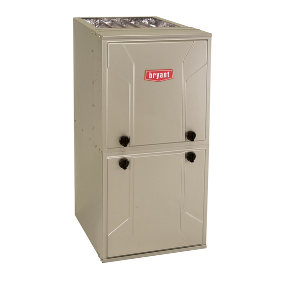
Bryant 926TB Manuals
Manuals and User Guides for Bryant 926TB. We have
1
Bryant 926TB manual available for free PDF download: Installation, Start-Up, Operating And Service And Maintenance Instructions
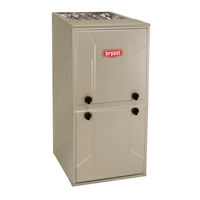
Bryant 926TB Installation, Start-Up, Operating And Service And Maintenance Instructions (85 pages)
TWO-STAGE, VARIABLE-SPEED ECM MULTIPOISE CONDENSING GAS FURNACE
Brand:
Bryant
| Category:
Furnace
| Size: 11.81 MB
Table of Contents
Table of Contents
1
Sections
1
Important
2
Furnace Reliability Hazard
4
Fire Hazard
4
Safety Considerations
4
Introduction
5
Freeze Protection and Return Air Temperature
5
Loose Parts Bag
5
Minimum Clearances to Combustible Materials
5
General Installation
6
Combustion and Ventilation Air
6
Codes and Standards
6
Electrostatic Discharge (Esd) Precautions
6
Location
7
General
7
Multipoise Orientations
8
Location Relative to Cooling Equipment
8
Prohibited Installations
8
Installation in a Garage
8
Direct Vent (2- - Pipe) Applications
9
Ventilated Combustion Air Applications
9
Outdoor Combustion Air Method
9
Air for Combustion and Ventilation
9
Combination of Indoor and Outdoor Air
10
Standard Method
10
Indoor Combustion Aire NFPA & AGA
10
EXAMPLES: Determining Free Area
11
Minimum Free Area Required
11
Minimum Space Volumes
11
Upflow Orientation
12
Downflow Orientation
12
To Relocate the Condensate Trap
12
Condensate Trap
12
Horizontal Right Trap Configuration
13
Property Damage Hazard
13
Horizontal Left Configuration
13
Condensate Drain Connection
13
Upflow/Downflow Orientation
14
For Left Side Condensate Drain Connection
14
Knockout Removal
14
For Right Side Condensate Drain
14
Tip from Contractors
15
Horizontal Orientation
15
Modify Rubber Drain Elbow
15
Evaporator Coil
16
Example of Field Drain Attachment (Not Allowed)
16
Supply Air Connections
17
Example of Field Drain Attachment
17
Upflow Installation
17
Installation
17
Return Air Connections
18
Bottom Return Air Inlet
18
Side Return Air Inlet
18
Downflow Installation
18
Horizontal Installation
19
Platform Furnace Support
19
Suspended Furnace Support
19
Roll-Out Protection
19
Upflow Return Air Configurations and Restrictions
20
Rollout Protection Required
21
Suspended Furnace Installation
21
Working Platform for Attic Installation
21
Filter and Return Duct Sizing
22
Removing Bottom Closure Panel (2 Screws)
22
Filter Arrangement
22
Air Filter Located in Filter Cabinet
24
Optional Media Filter
24
Installation on Combustible Flooring
25
Opening Dimensions
25
General Requirements
30
Return Duct Sizing
30
Air Ducts
30
Gas Piping
30
Gas Valve with Tower Pressure Ports
31
Typical Gas Pipe Arrangement
31
– Maximum Capacity of Pipe
31
Alternate Gas and Electric Entry
32
Gas Entry
32
Gas Pipe Grommet
32
Electrical Connections
32
115-V Wiring
33
J-Box Installation
33
Installing J- -Box (When Used)
33
External Electrical Box on Furnace Casing
34
Power Cord Installation in Furnace J-Box
34
BX Cable Installation in Furnace J-Box
34
24-V Wiring
34
Alternate Power Supplies
35
Thermostats
35
Accessories
35
Electrical Data
35
Typical Two- -Stage Field Wiring Diagram
36
Example of Variable Speed Furnace Control
36
Thermostat Wiring Diagrams
37
Notes for Thermostat Wiring Diagrams
38
Venting
38
Special Venting Requirements for Installations in Canada
38
Materials
39
Venting Systems
40
Installation
40
Ventilated Combustion Air Systems
41
Locating the Vent Termination
41
Vent Termination Kit for Direct Vent (2- -Pipe) Systems
41
Combustion Air and Vent Piping Insulation
44
Configure the Furnace
44
Carbon Monoxide Poisoning Hazard
44
Maximum Equivalent Vent Length
44
Near Furnace Vent Connections
45
Install the Vent and Combustion Air Pipes
45
Combustion Air Pipe Attachment
45
Upflow Left Configuration
45
Downflow Vertical
46
Downflow Right Configuration
46
Upflow Vertical Vent
46
Upflow Right Configuration
46
Horizonal Left ---Left Vent Configuration
47
Horizontal Right ---Left Vent Configuration
47
Horizontal Left ---Right Vent Configuration
47
Horizontal Right ---Right Vent Configuration
47
Notes for Venting Options
48
Vent Coupling and Adapter
48
Inducer Vent Elbow
48
– Hanger Spacing
49
Vent Pipe Flush Showing Coupling
50
Vent Pipe Flush with Adapter
50
For Polypropylene Venting Systems
50
Installing the Vent Termination
51
Roof Terminations
51
2-Pipe and 1-Pipe Vent Termination
51
Inducer Outlet Restrictor
51
Elbow Configurations
53
Vent Terminal Configurations
53
Deductions from Maximum Equivalent Vent Length
53
Venting System Length Calculations
54
Inside Corner Terminations
55
Setup Switches
60
Prime Condensate Trap with Water
60
Continuous Fan (CF) Setup Switches
60
Start- -Up, Adjustment, and Safety Check
60
Adjustments
61
Purge Gas Lines
61
Orifice Hole
61
Priming Condensate Trap
61
Adjust Manifold Pressure
62
Check Inlet Gas Pressure
62
Adjust Temperature Rise
63
Clocking the Meter
63
Burner Flame
63
To Lock the Furnace in High Heat
64
Adjust Blower off Delay (Heat Mode)
64
Adjust Thermostat Heat Anticipator
64
To Lock the Furnace in Low Heat
64
Check Safety Controls
65
Checklist
65
Service
66
LED Code
66
Status
66
Component Test
66
Dip Switch
67
Furnace Setup Switch Description
67
Airflow Selection
67
– Gas Rate (CU Ft./Hr)
68
– Blower off Delay Setup Switch
68
– Altitude Derate Multiplier for USA
68
Orifice Size and Manifold Pressure (In. W.C.) for Gas Input Rate
69
Two-Stage Furnace
69
Service and Maintenance Procedures
70
Electrical Controls and Wiring
71
Component Self- - Test
71
Troubleshooting
71
Retrieving Stored Status Codes
71
Care and Maintenance
72
Cleaning And/Or Replacing Air Filter
72
Blower Motor and Wheel Maintenance
72
Blower Assembly
73
Burner Assembly
74
Cleaning Burners and Flame Sensor
74
Servicing Hot Surface Igniter
75
Igniter Position - - Side View
75
Flushing Collector Box and Drainage System
75
To Reinstall Burner Assembly
75
Checking Heat Pad Operation
76
Cleaning Condensate Drain and Trap
76
Cleaning Heat Exchangers
76
Primary Heat Exchangers
76
Winterization
77
Cleaning Heat Exchanger Cell
77
Wiring Diagrams
77
Secondary Heat Exchangers
77
Inducer Prepurge Period
78
Sequence of Operation
78
Cooling Mode
79
Single- -Speed Cooling
79
Dehumidification Mode
80
Heat Pump
80
Continuous Blower Mode
80
Troubleshooting Guide
81
Parts Replacement Information Guide
84
Casing Group
84
Model Nomenclature
84
Advertisement
Advertisement
Related Products
Bryant 926TA A SERIES
Bryant 926TA30040V14
Bryant 926TA36040V17
Bryant 926TA36060V14
Bryant 926TA42060V17
Bryant 926TA60080V21
Bryant 926TA60100V21
Bryant 926TA66120V24
Bryant 926TC
Bryant 926TA48080V17
Bryant Categories
Furnace
Air Conditioner
Heat Pump
Thermostat
Fan
More Bryant Manuals
Login
Sign In
OR
Sign in with Facebook
Sign in with Google
Upload manual
Upload from disk
Upload from URL