Sign In
Upload
Manuals
Brands
Bradford White Manuals
Boiler
OmniTech BONH1750
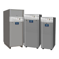
Bradford White OmniTech BONH1750 Manuals
Manuals and User Guides for Bradford White OmniTech BONH1750. We have
2
Bradford White OmniTech BONH1750 manuals available for free PDF download: Installation And Operation Instructions Manual, Assembly, Installation And Operation Instructions
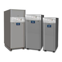
Bradford White OmniTech BONH1750 Installation And Operation Instructions Manual (148 pages)
Category II and IV Venting with touchscreen controls
Brand:
Bradford White
| Category:
Boiler
| Size: 33.97 MB
Table of Contents
Table of Contents
2
SECTION 1 General Information
5
A Introduction
5
B Warranty
5
C Model Identification
5
D Safety Notes
6
E Unit Dimensions and Components
8
Model 1250 / 1500
8
Model 1750
10
Models 2000 / 2500
12
F Unpacking
14
G Locating the Unit
14
H Clearances
14
SECTION 2 Venting and Combustion Air 2.A General Venting Info
15
Vent and Air Pipe Sizing
15
A.1.A Category II Vent
16
A.1.B Category IV Vent
16
Vent and Air Pipe Material
16
Exhaust Vent Terminal
17
Air for Combustion and Ventilation
17
A.4.A Combustion Air from Room
17
A.4.B Ducted Combustion Air
17
B Common Venting
18
Common Venting
18
Removing a Boiler from an Existing Common Vent System
18
Locating Vent & Combustion Air Terminals
20
Side Wall Vent Terminal
20
Side-Wall Combustion Air Terminal
21
Vertical Vent Terminal
21
Vertical Combustion Air Terminal
21
Outdoor Installation
23
Installations in the Commonwealth of Massachusetts
23
SECTION 3 Gas Supply and Piping
24
Gas Supply and Piping
24
Gas Pipe Sizing
25
SECTION 4 Water Flow and Headloss Data
25
General Water Flow Information
25
Boiler Water Flow & Headloss Data
26
Water Heater Flow and Headloss Data
26
Recovery Data
27
SECTION 5 Piping
28
Boiler Water Piping
28
Boiler Water Connections
28
Cold Water Make-Up
28
Freeze Protection
28
Suggested Boiler Piping Schematics
29
Water Heaters
32
Water Quality
32
Heater Water Connections
32
Cold Water Make-Up
32
Freeze Protection
32
Suggested Piping Schematics
32
SECTION 6 Condensate Drain Trap
34
SECTION 7 Electrical Connections
34
Installation Warnings
34
Main Power Connections
35
Main Power Data
35
Control Panel Layout
36
Field Connections
36
Power
37
Boiler Pump
37
Dry Contacts
37
Alarm Bell
37
Sensors
37
Heat Demands
38
Spare Inputs
38
Inputs, BMS
38
Outputs, Pump
38
Dry Contacts (Run & Alarm)
38
RS 485 for Cascade (Lead Lag)
38
Rs485 Bms
40
Modbus/Bacnet Memory Map
41
Wiring Diagrams, High Voltage
44
Ladder Diagrams
49
Wiring Diagram
56
SECTION 8 Control Operation
58
The Home Screen
58
Home Screen Active Icons
58
Keypad Operations
59
Login to Lock / Unlock the Disp Screen
60
Quick Start
61
Central Heat)
61
CH1 (Central Heat, One) 1
62
CH2 (Central Heat, Two) 2
62
DHW (Domestic Hot Water)
62
Outdoor Reset
63
Warm Weather Shut down
63
Anti-Short Cycle
64
Time & Date
64
Configuration
65
Central Heat)
65
D.1
66
D.1.A CH1 (Central Heat, One)
66
D.1.A.1 PID Low
67
D.1.A.2 PID High
67
D.1.B CH2 (Central Heat, Two)
67
DHW (Domestic Hot Water)
68
Outdoor Reset
69
Cascade (All about Lead / Lag)
70
D.4.A Cascade Parameters
75
D.4.A.1 Base / Drop Load
76
D.4.B Rotation
76
D.4.B.1 Rotation Setup
77
D.4.C Redundancy
77
Pumps
78
D.5.A Variable Speed Pump Control
79
Manual Firing Rate
80
Temp Limits
80
D.7.A Delta T Parameters
81
D.7.B Flue Limitation Parameters
81
D.7.C Outlet Limitation Parameters
81
External
82
D.8.A External - Remote Set Point
83
D.8.B External Firing Rate
83
Time & Date
84
Miscellaneous Features
84
D.10.A Demands Priorities
85
D.10.B Anti-Short Cycle
85
D.10.C Warm Weather
86
D.10.D COM Port, BMS
87
D.10.E Temperature Conversion
88
D.10.F Anti-Frost
88
Login
89
E Service Screens
90
Burner
90
Digital I/O Inputs
91
E.2.A Digital Outputs
91
Analog I/O
92
Screen Settings Timeout
93
History
93
Restart Touchscreen & Recalibrate
94
Factory Reset
94
HMI Model OEM Only
94
BIC Model OEM Only
94
Both Models. OEM Only
94
About the Firmware of the Touchscreen
94
Dev Fan
94
Fan Settings
94
F Messages and USB
95
Messages
95
USB Functionality
95
G Active Demands
96
SECTION 9 Gas Valve Touchscreen, Menus and Descriptions
97
About the Gas Valve
97
Menu Structure (Example)
98
Gas Valve Display Navigation and Menus
98
Fuel Air Ratio & Ignition, Menus
101
Oem
101
Ignition Menu
102
Base Curve Menu
103
Correction Curve Menu
103
Summary Menu
104
Load & Save Menu
104
Diagnostics
105
Verification Menu
106
Gas Valve Password & Login Menu
108
SECTION 10 Parameter Tables
109
SECTION 11 Initial Startup Instructions
113
Filling the Boiler System
113
Initial Operation
114
Initial Burner Operation
114
Shutting down the Unit
114
Restarting the Unit
114
Combustion Setup
115
Firing Rate for Boiler
115
Combustion at the Gas Valve Display
116
SECTION 12 Maintenance
117
System Maintenance
117
Maintenance Notes
117
Burner
117
Gas Valve / Venturi
117
Main Omnitherm Controller
118
Valve Control / Display
118
Spark & Flame Sensors Electrodes
118
Blower
118
Heat Exchanger Tubes
118
Gas Pressure Switches
118
SECTION 13 Troubleshooting
120
Error Codes
120
SV2 Fault Codes
124
SECTION 14 Replacement Parts
131
General Information
131
Component Illustrations, Parts Lists, and Part Numbers
131
Advertisement
Bradford White OmniTech BONH1750 Assembly, Installation And Operation Instructions (132 pages)
Brand:
Bradford White
| Category:
Boiler
| Size: 31.36 MB
Table of Contents
Table of Contents
2
SECTION 1 General Information
5
A Introduction
5
B Warranty
5
C Model Identification
5
D Safety Notes
6
E Unit Dimensions and Components
8
Model 1250 / 1500
8
Model 1750
10
Models 2000 / 2500
12
F Unpacking
14
G Locating the Unit
14
H Clearances
14
SECTION 2 Venting and Combustion Air
15
A General Venting Info, Cat I and Cat III
15
Vent and Air Pipe Sizing
15
A.2.A Combustion Air from Room
15
A.2.B Ducted Combustion Air
16
B Category I Venting
17
Category I Vent
17
Common Venting Systems
17
Common Vent Test - Boilers
18
C Category III Venting
19
Category III Vent
19
Exhaust Vent Terminal
19
Vent and Air Pipe Material
19
Vent Adapters
19
D Locating Vent & Comb Air Terminals
20
Side Wall Vent Terminal Category Lll Only
20
Side-Wall Combustion Air Terminal Category L and Lll
20
Vertical Vent Terminal Category L and Lll
20
Vertical Combustion Air Terminal Category L and Lll
20
E Outdoor Installation
22
F Installations in the Commonwealth of Massachusetts
23
SECTION 3 Gas Supply and Piping
23
A Gas Supply and Piping
23
B Gas Pipe Sizing
24
SECTION 4 Water Flow and Headloss Data
24
A General Water Flow Information
24
B Boiler Water Flow & Headloss Data
25
C Water Heater Flow and Headloss Data
25
Recovery Data
26
SECTION 5 Piping
27
Boiler Water Piping
27
Boiler Water Connections
27
Cold Water Make-Up
27
Freeze Protection
27
Suggested Boiler Piping Schematics
28
Water Heaters
32
Water Quality
32
Heater Water Connections
32
Cold Water Make-Up
32
Freeze Protection
32
Suggested Piping Schematics
32
SECTION 6 Condensate Drain Trap
34
SECTION 7 Electrical Connections
34
Installation Warnings
34
Main Power Connections
35
Main Power Data
35
Control Panel Layout
36
Field Connections
36
Power
37
Boiler Pump
37
Dry Contacts
37
Alarm Bell
37
Sensors
37
Heat Demands
38
Spare Inputs
38
Inputs, BMS
38
Outputs, Pump
38
Dry Contacts (Run & Alarm)
38
RS 485 for Cascade (Lead Lag)
38
Rs485 Bms
38
Modbus/Bacnet Memory Map
40
Wiring Diagrams - High Voltage
44
Logic Diagrams
49
SECTION 8 Control Operation
54
The Home Screen
54
Home Screen Active Icons
54
Keypad Operations
55
Login to Lock / Unlock the Disp Screen
56
Quick Start
57
Central Heat)
57
CH1 (Central Heat, One) 1
58
CH2 (Central Heat, Two) 2
58
DHW (Domestic Hot Water)
58
Outdoor Reset
59
Warm Weather Shut down
59
Anti-Short Cycle
60
Time & Date
60
D Configuration
61
Central Heat)
62
D.1.A CH1 (Central Heat, One)
62
D.1.A.1 PID Low
63
D.1.A.2 PID High
63
D.1.B CH2 (Central Heat, Two)
63
DHW (Domestic Hot Water)
64
Outdoor Reset
65
Cascade
66
D.4.A Cascade Parameters
67
D.4.B Rotation
68
D.4.B.1 Rotation Setup
68
D.4.C Redundancy
69
Pumps
70
D.5.A Vari-Prime
71
Manual Firing Rate
72
Temp Limits
72
D.7.A Delta T Parameters
73
D.7.B Flue Limitation Parameters
73
D.7.C Outlet Limitation Parameters
73
External
74
D.8.A External - Remote Set Point
75
Time & Date
75
Miscellaneous Features
76
D.10.A Demands Priorities
77
D.10.B Anti-Short Cycle
77
D.10.C Warm Weather
78
D.10.D COM Port, BMS
79
D.10.E Temperature Conversion
80
D.10.F Anti-Frost
80
Login
81
E Service Screens
82
Burner
82
Digital I/O Inputs
83
E.2.A Digital Outputs
83
Analog I/O
84
Screen Settings Timeout
85
History
85
Restart Touchscreen & Recalibrate
86
Factory Reset
86
HMI Model OEM Only
86
BIC Model OEM Only
86
Both Models. OEM Only
86
About the Firmware of the Touchscreen
86
Dev Fan
86
Fan Settings
86
F Messages and USB
87
Messages
87
USB Functionality
87
Active Demands
88
SECTION 9 Gas Valve Touchscreen, Menus and Descriptions
89
About the Gas Valve
89
Menu Structure (Example)
90
Gas Valve Display Navigation and Menus
90
Fuel Air Ratio & Ignition, Menus
93
Oem
93
Ignition Menu
94
Base Curve Menu
95
Correction Curve Menu
95
Summary Menu
96
Load & Save Menu
96
Diagnostics
97
Verification Menu
98
Gas Valve Password & Login Menu
100
SECTION 10 Parameter Tables
101
SECTION 11 Initial Startup Instructions
105
Filling the Boiler System
105
Initial Operation
106
Initial Burner Operation
106
Shutting down the Unit
106
Restarting the Unit
106
Combustion Setup
107
Firing Rate for Boiler
107
Combustion at the Gas Valve Display
108
SECTION 12 Maintenance
109
System Maintenance
109
Maintenance Notes
109
Burner
109
Gas Valve / Venturi
109
Main Controller
110
Valve Control / Display
110
Spark & Flame Sensors Electrodes
110
Blower
110
Heat Exchanger Tubes
110
Gas Pressure Switches
111
SECTION 13 Troubleshooting
112
Error Codes
112
SECTION 14 Replacement Parts
116
General Information
116
Component Illustrations, Parts Lists, and Part Numbers
116
Advertisement
Related Products
Bradford White OmniTech BONH1250
Bradford White OmniTech BONH1500
Bradford White OmniTech BONH2000
Bradford White OmniTech BONH2500
Bradford White OmniTech BONV2000
Bradford White OmniTech BONV1750
Bradford White OmniTech BONV1500
Bradford White OmniTech BONV1250
Bradford White Brute OmniTech BONV2500
Bradford White Brute BLXH 150 MBH
Bradford White Categories
Water Heater
Boiler
Heat Pump
Gas Heater
Heating System
More Bradford White Manuals
Login
Sign In
OR
Sign in with Facebook
Sign in with Google
Upload manual
Upload from disk
Upload from URL