Sign In
Upload
Manuals
Brands
Bosch Manuals
Cell Phone
DS7240-UK
Bosch DS7240-UK Manuals
Manuals and User Guides for Bosch DS7240-UK. We have
1
Bosch DS7240-UK manual available for free PDF download: Reference Manual
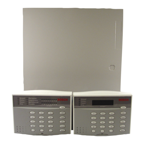
Bosch DS7240-UK Reference Manual (166 pages)
Control/Communicator
Brand:
Bosch
| Category:
Cell Phone
| Size: 7.03 MB
Table of Contents
Figure 1: Panel Wiring Connections
1
Table 1: Terminal Descriptions
2
Table of Contents
4
Figure 2: Enclosure Mounting
10
Figure 3: Battery Connections
10
Figure 4: Telephone Connections
11
Figure 5: Jumper Plug Configuration
11
Figure 6: Wiring a Keypad to the Panel
11
Table 2: Keypad Address Pin Settings
11
Table 3: Keypad Wire Lengths
11
Figure 7: Keypad External Power Supply Connections
12
Figure 8: Keyswitch Wiring
12
Figure 9: Tamper-Wired Zone Wiring
13
Figure 10: Single Zone Sensor Loop Wiring (no EOL)
13
Figure 11: Typical 4-Wire Smoke Detector Wiring
13
Figure 12: PO 1 Wiring
14
Figure 13: PO 2 - PO 4 Wiring
14
Figure 14: RF3227E Address Jumper Settings
15
Figure 15: RF3227E to Panel Connections
15
Figure 16: DX2013 Mounting Locations
15
Figure 17: Mounting the DX2013 (Step 1)
16
Figure 18: Mounting the DX2013 (Step 2)
16
Figure 19: Mounting the DX2013 (Step 3)
16
Figure 20: DX2010 to Panel Connections
17
Figure 21: External Power Supply Connections
17
Figure 22: DX2010 Auxiliary Output Connections
17
Figure 23: DX2010 Tamper Input Wiring
18
Figure 24: DX2010 Wire Jumper Connections
18
Figure 25: DX2010 Tamper-Wired Loop Configuration
18
Table 4: DX2010 Address Settings
18
Figure 26: DX2010 DIP Switch Configuration
19
Figure 27: DX2010 Status LED Location
19
Table 5: DX2010 DIP Switch Settings
19
Figure 28: DX3013 Mounting Locations
20
Figure 29: Mounting the DX3013 (Step 1)
20
Figure 30: Mounting the DX3013 (Step 2)
20
Figure 31: Mounting the DX3013 (Step 3)
21
Figure 32: Wiring the DX3010 to the Panel
21
Figure 33: DX3010 External Power Supply Connections
21
Table 6: DX3010 Wire Lengths
21
Figure 34: DX3010 DIP Switch Configuration
22
Figure 35: DX4010 PCB
22
Table 7: DX3010 Addresses
22
Table 8: DX3013 Address DIP Switch Settings
22
Figure 36: DX4010 to Panel Connections
23
Figure 37: DX4010 External Power Supply Connections
23
Figure 38: Direct Connect DIP Switch Setting
23
Figure 39: Remote Programming Direct Connection
23
Figure 40: DX4010 P2 Jumper Pin Settings
24
Figure 41: DX4010 P3 Jumper Pin Settings
24
Figure 42: RS-232 Device DIP Switch Setting
24
Figure 43: DX4010 DB9 Connector Layout
24
Table 9: DX4010 Diagnostic LED Functions
24
Table 10: DX4010 DB9 Pin Configuration
24
Figure 44: Panel Reset Display
25
Figure 45: System Status LED
25
Table 11: System Status LED Operation
25
Figure 46: Installer Keypad Connections
26
Figure 47: Adding RF ID Codes Menu Display
27
Figure 48: RF ID Code Display
27
Figure 49: Test RF Devices Display
27
Figure 50: RF Device Test Status Display
27
Figure 51: RF ID Code Entry Display
28
Figure 52: Initial Programming Display
28
Figure 53: Selecting an Address
28
Figure 54: Editing Data Digits
29
Figure 55: Reset Display Screen
29
Table 12: Key/Character Assignments
29
Figure 56: PK32 to Panel Connections
30
Figure 57: Sample Programming Entry
31
Table 13: Option Parameter Table Example
31
Figure 58: Routing Destinations
32
Table 14: Phone Number Entry Selections
32
Tests
47
System Test Configuration Options
47
System Test Enable Options
48
Walk Test Configuration Options
49
Walk Test Enable Options
50
Automatic Test Report Options
51
Automatic Test Report Time
51
Automatic Test Report Interval
52
Test Report Routing
52
Programming Options
53
Remote Programming Options
53
Local Programming Options
54
Global Open/Close Options
55
Arming Options 1
55
Arming Options 2
56
Bypass/Force Arm Limit
56
Open/Close Reporting Options
57
Opening/Closing Report Routing
58
Exit Time Restart
58
Entry Delay Time 1 (2)
59
Perimeter Only Mode Delay Time
60
Exit Delay Time 1 (2)
60
Areas
62
Area # Account Number
62
Table 15: Account Number Entry Selections
62
Area # Opening/Closing Reporting Options
63
Lock Area # Reporting
64
Authority Level Configuration
64
Authority Level Option 1
64
Authority Level Option 2
65
Authority Level Option 3
66
Authority Level Option 4
66
Authority Level Option 5
67
Authority Level Option 6
67
Authority Level Option 7
68
Authority Level Option 8
68
Authority Level Option 9
69
Authority Level Option 10
70
Authority Level Option 11
70
Authority Level Option 12
71
Authority Level Option 13
71
Authority Level Option 14
72
Authority Level Option 15
72
PIN Configuration, Installer PIN
72
PIN Length
72
User Tamper Options
73
User Tamper Retry Count
73
User Tamper Lockout Time
74
Installer PIN
74
Users
75
Table 16: User Configuration Addresses & Defaults
75
PIN, User
76
Authority Level, User
77
Table 17: Authority Level Configuration Functions
77
Area Option, User
78
Keypads
78
Table 18: Keypad Data Bus Addresses
78
Keypad # Options
79
Table 19: DS7446 Keypad LED Functions
79
Keypad # Area
80
Help Function Keys and Duress Parameters
81
Area Options for Help Function Keys
81
Alarm Response for Help Function Keys
82
Alarm Output Option for Help Function Keys
82
Help Function Key Reports, Ack Beep at Keypad Options
83
Duress Reporting Options
83
Help Function Key and Duress Report Routing
84
Enable Keypad Tamper Response
84
Guard Code Options
85
Locations
86
Table 20: Location Configuration Parameters
86
Location ##, Device
88
Location ##, Zone Function
89
Table 21: Zone Function Type Selections
89
Location ##, Area
92
Location ##, Zone Number
92
Zone Function Configuration
93
Table 22: Zone Function Configuration Parameters
93
Zone Function Type, Zone Function
94
Table 23: Zone Function Type Options
94
Pulse Count
96
Pulse Count Time
96
Table 24: Pulse Count Time Selections
96
Options 1, Zone Function
97
Options 2, Zone Function
99
Reporting Enable, Trouble Response Options, Zone Function
100
Alarm Report Routing, Zone Function
101
Restoral Report Routing, Zone Function
101
Global Zone Configuration
102
On-Board Location EOL Resistor Value
102
Table 25: EOL Resistor Location Pairing
102
Zone Response Options (for All Zones)
103
Bypass/Force Arm Report Routing
103
Swinger Count for Alarm Output
104
Swinger Count for Zone Reports
104
Bypass, Swinger Shunt, Sensor Trouble Report Options
105
Sensor Monitor Time
105
Alarm Event Abort Window
105
Zone Trouble, Restoral from Trouble Report Routing
106
Global Output Configuration
107
Global Output Options
107
Bell Time
108
Siren Warble Frequency
108
Siren Output Volume
108
Strobe Output Type Options
109
Outputs
110
Table 26: Output Configuration Parameters
110
Area, Output
111
Function, Output
112
Table 27: Output Function Types
112
Mode (Steady, Pulse, One Shot), Output
115
Table 28: Output Mode Options
115
Base, Output
116
Multiplier
116
Configuring Steady, Pulse and One Shot Mode
116
Table 29: Pulse Mode Configuration
116
Table 30: One Shot Mode Configuration
116
Skeds
117
Type, Sked
117
Table 31: Sked Configuration Parameters
117
Assign (Area or Output), Sked
118
Time, Sked
118
Days Option 1, Sked
119
Days Option 2, Sked
119
Data Bus Device Configuration
120
Premises RF Receiver Options
120
Premises RF Receiver, Supervision Interval
120
RF Jam Detect Level
121
DX4010 Module Output Configuration
121
DX4010 Module Baud Rate Configuration
121
DX4010 Module Parity, Flow Control, Stop Bit Configuration
122
DX8010 Module Access Options
122
DX2010 Configuration Options
123
Miscellaneous System Trouble Options
124
Text Entry Parameters
125
Call for Service Text
125
Table 32: Key/Character Assignments
125
Keypad Help Function Keys Text
126
Area Name Text
126
Area Idle Text
126
Location Text
127
Table 33: Location Text Addresses/Defaults
127
RF Keypads
128
RF Keypad # Options
128
RF Keypad # Area
128
Table 34: RF Keypad Data Bus Addresses
128
RF Keyfobs
129
RF Keyfob Receiver Assignment Options
129
RF Keyfob Options
130
Factory Default
130
Tamper Response Configuration
131
Tamper Alarm/Trouble Options
131
System Alarm Reports/Output Options
132
Exit Delay Configuration
132
Contact Set/Exit Delay Cancel Zone Options
132
Exit Terminator Zone Options
133
Panel Arming Options
134
Confirmation Alarm Timer
135
Reporting Format Configuration
136
Personal Dialing Format Configuration
136
BSIA Fast Format Configuration
137
Table 35: BSIA Fast Format Configuration Parameters
137
Basic Pager Display
138
Table 36: Phone Number Selections
140
Part IV: Reference Materials
141
Troubleshooting
141
Arming Issues
141
Zone Issues
141
Programming Issues
142
Keypad Issues
143
Miscellaneous Issues
143
Data Bus Address Quick Reference
143
Table 37: Data Bus Address Quick Reference
143
BSIA Fast Format
144
SIA 300 with Text Blocks
144
Personal Dialing Format
145
Table 38: Personal Dialing Format Event Groups
145
Table 39: Personal Dialing Format Specifications
145
Dialing Attempt Tables
146
Destination 1 Only
146
Destination 2 Only
146
Destination 1 and Destination 2
147
Call for Service Details
148
Table 40: Call for Service Details
148
Keypad Quick Reference
149
System Arming/Disarming Functions
149
Other System Functions
149
History Log
150
Figure 59: History Log Display
150
Table 41: History Log Display Descriptions
150
Panel Events and Reporting Formats
151
Table 42: Panel Events and Reporting Formats
151
Glossary
161
Advertisement
Advertisement
Related Products
Bosch DS7060
Bosch D9068
Bosch DS7200V2-EXP
Bosch DS7200V2-UK
Bosch DS7220V2
Bosch DS7240V2
Bosch DS7445
Bosch DS7447E
Bosch DS7447
Bosch DS7446KP
Bosch Categories
Dishwasher
Washer
Oven
Power Tool
Dryer
More Bosch Manuals
Login
Sign In
OR
Sign in with Facebook
Sign in with Google
Upload manual
Upload from disk
Upload from URL