Sign In
Upload
Manuals
Brands
Agilent Technologies Manuals
Computer Hardware
C-Size VXIbus Systems
Agilent Technologies C-Size VXIbus Systems Manuals
Manuals and User Guides for Agilent Technologies C-Size VXIbus Systems. We have
1
Agilent Technologies C-Size VXIbus Systems manual available for free PDF download: Configuration Manual
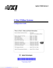
Agilent Technologies C-Size VXIbus Systems Configuration Manual (178 pages)
C-Size VXIbus Systems
Brand:
Agilent Technologies
| Category:
Computer Hardware
| Size: 3.13 MB
Table of Contents
Configuration Guide
1
Table of Contents
3
Warranty
7
Warnings
8
Safety Symbols
8
Using the C-Size Configuration Guide and Agilent VIC
11
For more Information
12
Terms Used in this Manual
13
Procedure 1: Configure the VXI Mainframe
15
Step-1 : Connect Mainframe Safety Ground (if Necessary)
16
Grounding Procedure
16
Step-2 : Connect the Power Cord
17
Step-3 : Where to Go Next
18
Procedure 2
19
Set up the VXI System Controller
19
Setting up the Agilent E1406A Command Module
20
E1406-1 : Set the Command Module as Resource Manager
21
E1406-2 : Set the Command Module as Slot 0 Device
22
E1406-3 : Set the Clock Source
23
E1406-4 : Set the Bus Request Level
24
E1406-5 : Configure the Command Module's Shared RAM
25
E1406-6 : Set the Command Module's Servant Area
26
E1406-7 : Set Command Module's Primary GPIB Address
27
E1406-8 : Install the Command Module into the Mainframe
28
E1406-9 : Connect Interface Cables
29
E1406-10 : Apply Power
31
Alternate Command Module Configurations
33
E1406-11 : Where to Go Next
35
Setting up a Series 700 Controller
36
System Configuration
36
Series 700-1 : Set up the Agilent E1482B Vxibus Extender Module
38
Series 700-2 : Set up the Agilent E1406A Command Module
41
Series 700-2A : Setting the Command Module Logical Address
42
Series 700-2B : Setting the Command Module Servant Area
42
Series 700-2C : Setting the Command Module Primary GPIB Address
43
Series 700-2D : Disabling the Command Module's Slot 0 Capability
44
Series 700-2E : Disabling the Command Module's Vmebus Time out Capability
44
Series 700-3 : Install the Agilent E1482B Extender Module in the Mainframe
46
Installing the E1406A Command Module
46
Series 700-4 : Connect the Mxibus and INTX Cables
47
Series 700-5 : Apply Power
48
Assigning Interrupt Lines
50
Series 700-6 : Where to Go Next
52
Setting up an Embedded V743 Controller
53
V743-1 : the V743 Configuration
53
The V743 Logical Address and Servant Area
55
V743-2 : Set up the Agilent E1406A Command Module
55
V743-2A : Setting the Command Module Logical Address
56
V743-2B : Setting the Command Module Servant Area
57
V743-2C : Setting the Command Module Primary GPIB Address
58
V743-2D : Disabling the Command Module's Slot 0 Capability
59
V743-3 : Install the V743 Controller in the Mainframe
60
Installing the E1406A Command Module
62
V743-4 : Apply Power
63
V743-4A : Enabling Shared Memory
64
V743-5 : Where to Go Next
66
Setting up an Embedded Agilent RADI-EPC7 486 Computer
67
EPC7-1 : Set the EPC7 as Slot 0 Device
68
EPC7-1A : Set the EPC7 as Non-Slot 0 Device if Using Multiple Mainframes
69
EPC7-2 : Install the EPC7 into the Mainframe
70
EPC7-3 : Install EXM Expansion Modules
72
EPC7-4 : Configure the Command Module to Work with the EPC7
73
EPC7-4A : Set the Command Module's Logical Address
74
EPC7-4B : Set the Command Module's Servant Area
75
EPC7-4C : Set the Command Module's Primary GPIB Address
76
EPC7-4D : Disable the Command Module's Slot 0 and System Controller Capability
77
EPC7-5 : Connect Interface Cables
78
EPC7-6 : Apply Power
79
EPC7-7 : Where to Go Next
81
Procedure 3
83
Set up the System for Multiple Mainframes
83
Mxibus-1 : Set up VXI-MXI Modules for Slot 0
86
Mxibus-2 : Set VXI-MXI Modules for Non-Slot 0
87
Mxibus-3 : Remove the Terminating Networks from Middle VXI-MXI Modules
91
Mxibus-4 : Set the VXI-MXI Module's Logical Address
92
Resource Manager
98
Mxibus-5 : Disable the Vmebus Timeout on Other Modules (VME BTO)
102
Mxibus-6 : Install VXI-MXI Modules into Mainframes
104
Mxibus-7 : Connect Interface Cables
106
Mxibus-8 : Apply Power
107
Mxibus-9 : Where to Go Next
107
Procedure 4
109
Configure and Install Instruments
109
Step-1 : Download Instrument Drivers
111
Step-2 : Set Instrument Logical Addresses
112
Step-3 : Install A- and B-Size Modules
116
Step-4 : Install C-Size Modules
119
Step-5 : Install a Chassis Shield
122
Step-6 : Install Backplane Connector Shields
123
Step-7 : Install Faceplate Panels
124
Step-8 : Where to Go Next
125
Procedure 5: Apply Power
127
Agilent E1406 Command Module with an External Computer
127
HP 9000 Series 700 Computer
130
Agilent E1497A/ E1498A Embedded V743 Controller
133
Agilent RADI-EPC7 Embedded 486 Computer
135
Where to Go Next
139
Procedure 6
141
System Programming and Debugging
141
COMM1 : Verify Communication with the Instruments
142
COMM1A : GPIB Addressing
142
COMM1B : Embedded Controller Addressing
143
COMM1C : SICL Addressing
144
COMM1D : C-SCPI Addressing
145
Debugging Programs
146
DEBUG1 : Sending SCPI Commands
147
SCPI Command Structure
147
DEBUG2 : Verify the System Logical Addresses
148
DEBUG3 : Start each Program by Fully Resetting each Instrument
149
DEBUG4 : Query the Instrument for Errors
149
DEBUG5 : Query All Command Parameter Settings
150
DEBUG6 : Verify that the Amount of Data to be Entered Is Equal to the Amount of Data Generated
150
DEBUG7 : Check the Instrument's Arm-Trigger Subsystem
151
DEBUG8 : Execute Coupled Commands Within a Coupling Group
152
How to Execute Coupled Commands
152
DEBUG9 : Check for Command Synchronization Errors
153
Appendix A: Terms and Definitions
155
What Is the Resource Manager
156
What Are the Slot 0 Functions?
156
What Is the Command Module's 10 Mhz Clock Source
157
What Is the Command Module's Bus Request Level
157
10 Mhz Clock Source
157
Bus Request Level
157
Command Module Memory
157
What Is Command Module Memory
158
What Is the Servant Area
159
Servant Area
159
What Is the Command Module's Primary GPIB Address
161
Primary GPIB Address
161
What Is the VXI-MXI Module?
162
What Are the VXI-MXI Logical Address Windows
162
What Is an Instrument Identifier
163
What Are Virtual Instruments
163
Virtual Instruments
163
What Is the Logical Address
164
What Are Downloadable Instrument Drivers
165
What Display Terminals Can be Used
166
What Are Interrupt Lines
166
Appendix B
167
Appendix B : Configuration and Start-Up Errors
167
Checking for Instrument Errors
173
Advertisement
Advertisement
Related Products
Agilent Technologies Cary 4000
Agilent Technologies Cary 7000
Agilent Technologies Cary 3500
Agilent Technologies Varian CP-8400
Agilent Technologies ACQIRIS CC103
Agilent Technologies ACQIRIS CC105
Agilent Technologies ACQIRIS CC108
Agilent Technologies ACQIRIS CC108-800
Agilent Technologies Cary 600 Series
Agilent Technologies Cryogenic
Agilent Technologies Categories
Measuring Instruments
Laboratory Equipment
Test Equipment
Water Pump
Power Supply
More Agilent Technologies Manuals
Login
Sign In
OR
Sign in with Facebook
Sign in with Google
Upload manual
Upload from disk
Upload from URL