Sign In
Upload
Manuals
Brands
ABB Manuals
Power Supply
ACS880-304 +A018
ABB ACS880-304 +A018 Manuals
Manuals and User Guides for ABB ACS880-304 +A018. We have
1
ABB ACS880-304 +A018 manual available for free PDF download: Hardware Manual
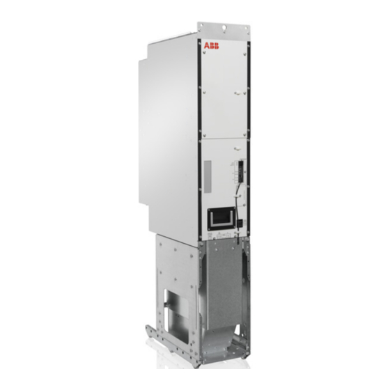
ABB ACS880-304 +A018 Hardware Manual (280 pages)
diode supply modules
Brand:
ABB
| Category:
Power Supply
| Size: 36.23 MB
Table of Contents
Effective: 2015
3
Table of Contents
5
Introduction to the Manual
15
Contents of this Chapter
15
Applicability
15
Safety Instructions
15
Target Audience
15
Contents of the Manual
16
Related Documents
16
Categorization by Frame Size and Option Code
16
Use of Item Designations
16
Terms and Abbreviations
17
Operation Principle and Hardware Description
19
Contents of this Chapter
19
Operation Principle
19
Main Circuit Diagram
20
6- and 12-Pulse Supply Units
21
Overview Diagrams
22
Overview Diagram of the Drive System
22
Overview Diagram - 1×D8T, 6-Pulse
23
Overview Diagram - 2×D8T, 6-Pulse
24
Overview Diagram - 3×D8T, 6-Pulse
25
Overview Diagram - 2×D8T, 12-Pulse
26
Hardware of the Supply Modules
27
Layout Drawings of the Supply Modules
28
Layout Drawing of D7T Supply Module
28
Connectors X50 and X53 of D7T Supply Module
29
Layout Drawing of D8T Supply Module
30
Connectors X50 and X53 of D8T Supply Module
31
Overview of Control Connections
32
Supply Unit Control Devices
33
Main Disconnector [Q1]
33
Auxiliary Voltage Switch [Q21]
33
Operating Switch [S21]
33
Emergency Stop Button [S61] and Emergency Stop Reset Button [S62]
33
The ACS-AP-I Control Panel
34
PC Connection
34
Fieldbus Control
34
Type Designation Label
35
Type Designation Key
36
Moving and Unpacking the Module
37
Contents of this Chapter
37
Moving and Lifting the Transport Package
37
Unpacking
38
Moving and Lifting the Module
38
Cabinet Construction
39
Contents of this Chapter
39
General Guidelines
39
Liability
39
Switching, Disconnecting and Protecting Solution
40
Auxiliary Control Cubicle
40
Incoming Cubicle
41
Example of the AC Fuse Cooling
41
RFI Filter
42
Configuration Overviews of the Supply Module Cubicles
43
Configuration Overviews - 6-Pulse
43
Configuration Overviews - 12-Pulse
45
Layout Drawings
47
Layout Drawing of the Supply Unit
47
Layout of Supply Module Cubicle - 2×D7T, 12-Pulse, in 600 MM Wide Rittal TS 8 Enclosure
48
MM Wide Rittal TS 8 Enclosures
49
Layout of Supply Module Cubicles - 2×D8T and 4×D8T, 12-Pulse, in 600 MM Wide Rittal TS 8 Enclosures
50
Installation Examples
51
Construction of Supply Module Cubicle - 2×D7T, 12-Pulse, Rittal TS 8
51
Kits for 2×D7T, 12-Pulse, Rittal TS 8
52
Stage 1: Installation of Common Parts
53
Stage 2: Module Installation Parts
54
Stage 3: Module Installation
55
Stage 4: AC Busbars to the Module
56
Stage 5: DC Busbars to the Module
57
Stage 6: Shroud Installation
58
Construction of Supply Module Cubicle - 1×D8T, 6-Pulse, Rittal TS 8
59
Kits for 1×D8T, 6-Pulse, Rittal TS 8
60
Stage 1: Installation of Common Parts
61
Stage 2: Module Installation Parts
62
Stage 3: Quick Connector Installation
63
Stage 4: DC Busbars to the Module
64
Stage 5: AC Busbars to Quick Connector
65
Stage 6: AC Busbar
66
Stage 7: Module Installation
67
Stage 8: Shroud Installation
68
Construction of Supply Module Cubicle - 1×D8T, 6-Pulse Generic Cabinet
69
Kits for 1×D8T, 6-Pulse Generic Cabinet
70
Construction of Supply Module Cubicle - 2×D8T, 6-Pulse, Rittal TS 8
71
Kits for 2×D8T, 6-Pulse, Rittal TS 8
72
Stage 1: Installation of Common Parts
73
Stage 2: Module Installation Parts
74
Stage 3: Quick Connector Installation
75
Stage 4: DC Busbars
76
Stage 5: AC Busbars to Quick Connector
77
Stage 6: AC Fuse Busbars Installation
78
Stage 7: Module Installation
79
Stage 8: Shroud Installation
80
Construction of Supply Module Cubicle - 2×D8T, 6- and 12-Pulse, Generic Cabinet
81
Kits for 2×D8T, 6- and 12-Pulse, Generic Cabinet
82
Construction of Supply Module Cubicle - 2×D8T, 12-Pulse, Rittal TS 8
83
Kits for 2×D8T, 12-Pulse, Rittal TS 8
84
Stage 1: Installation of Common Parts
85
Stage 2: Module Installation Parts
86
Stage 3: Quick Connectors
87
Stage 4: DC Busbar Installation
88
Stage 5: AC Busbars to Quick Connector
89
Stage 6: AC Busbars to Main AC Installation
90
Stage 7: Module Installation, DC Connection Flanges
91
Stage 8: Shroud Installation
92
Construction of Supply Module Cubicle - 3×D8T, 6-Pulse, Generic Cabinet
93
Kits for 3×D8T, 6-Pulse, Generic Cabinet
94
Electrical Installation
95
Contents of this Chapter
95
Safety and Liability
95
Related Documents
96
Basic Electrical Safety Precautions
96
General Notes
97
Static Electricity
97
Optical Components
97
Checking the Insulation of the Assembly
98
Supply Unit
98
Supply Cable
98
Checking the Compatibility with IT (Ungrounded) Systems
98
Connecting the Power Cables and Busbars
99
Connection Diagram - 1×D8T, 6-Pulse
99
Connection Diagram - 2×D8T, 6-Pulse
100
Connection Diagram - 3×D8T, 6-Pulse
101
Connection Diagram - 2×D8T, 12-Pulse
102
Connection Procedure
103
Connecting Auxiliary Power to the Diode Supply Module
105
Connection Procedure
105
Connecting Power Supply for the Control Unit
106
Connection Procedure
106
Connecting the Control Cables
107
Connection Diagram
107
Connection Procedure
107
Connecting a PC to the Supply Unit
109
Installing Option Modules
110
Installation Checklist
111
Contents of this Chapter
111
Before You Start
111
Checklist
111
Start-Up
113
Contents of this Chapter
113
Start-Up Procedure
114
Basic Checks with no Voltage Connected
114
Connecting Voltage to Input Terminals and Auxiliary Circuit
115
Setting the Supply Unit Parameters
115
Switching the Supply Unit on
115
On-Load Checks
115
Switching the Supply Unit off
116
Settings of Parameter 195.12
117
Maintenance
119
Contents of this Chapter
119
Maintenance Intervals
120
Cabinet
121
Cleaning the Interior of the Cabinet
121
Cleaning the Air Inlet Meshes (IP22 and IP42)
121
Cleaning the Door Air Inlets (IP54)
122
Cleaning the Outlet (Roof) Filters (IP54)
122
Power Connections
123
Tightening the Power Connections
123
Fuses
124
Checking and Replacing the DC Fuses of D7T Supply Module
124
Checking and Replacing the DC Fuses of D8T Supply Module
126
Checking and Replacing the AC Fuses
128
Fans
129
Replacing the Fan of the D7T Supply Module
129
Replacing the Fan of the D8T Supply Module
130
Replacing the Direct-On-Line Fan (Option +C188) of the D8T Supply Module
131
Replacing the Circuit Board Compartment Fan of the D8T Module
133
Replacing the Cabinet Cooling Fans
136
Cabinets with ABB Air Outlet Kits
136
Cabinets with Other Fan Types
136
Supply Module
137
Cleaning the Heatsink
137
Replacing the D7T Supply Module
138
Replacing the D8T Supply Module
141
Control Panel
145
Replacing the Control Panel Battery
145
Control Unit
146
BCU Control Unit Types
146
Memory Unit
146
Control Unit Battery
147
LEDS and Other Status Indicators
148
Reduced Run
149
Starting Reduced Run Operation
149
Resuming Normal Operation
150
Ordering Information
151
Contents of this Chapter
151
Kit Code
152
Diode Supply Units - 2×D7T, 12-Pulse
153
Diode Supply Modules - 2×D7T, 12-Pulse
153
Mechanical Installation Accessories - 2×D7T, 12-Pulse, Rittal TS 8
154
Installation Parts
154
Shrouds
154
AC Busbar Support
155
DC Busbars
155
Other Components and Tools - 2×D7T, 12-Pulse
155
Diode Supply Units - 1×D8T, 6-Pulse
156
Diode Supply Modules - 1×D8T, 6-Pulse
156
Mechanical Installation Accessories - 1×D8T, 6-Pulse, Rittal TS 8
157
Module Installation Parts
157
Shrouds
157
AC Busbars
158
AC Busbars to Quick Connector
158
DC Busbars
159
DC Connection Flanges
159
Mechanical Installation Accessories - 1×D8T, 6-Pulse, Generic Cabinet
160
Module Installation Parts
160
AC Busbars to Quick Connector
160
DC Busbars
161
DC Connection Flanges
161
Other Components and Tools - 1×D8T, 6-Pulse
161
Diode Supply Units - 2×D8T, 6-Pulse
162
Diode Supply Modules - 2×D8T, 6-Pulse
162
Mechanical Installation Accessories - 2×D8T, 6-Pulse, Rittal TS 8
163
Module Installation Parts
163
Shrouds
163
AC Busbars
164
AC Busbars to Quick Connector
164
DC Busbars
165
DC Connection Flanges
165
Mechanical Installation Accessories - 2×D8T, 6-Pulse, Generic Cabinet
166
Module Installation Parts
166
AC Busbars to Quick Connector
166
DC Busbars
167
DC Connection Flanges
167
Other Components and Tools - 2×D8T, 6-Pulse
167
Diode Supply Units - 2×D8T, 12-Pulse
168
Diode Supply Modules - 2×D8T, 12-Pulse
168
Mechanical Installation Accessories - 2×D8T, 12-Pulse, Rittal TS 8
169
Module Installation Parts
169
Shrouds
169
AC Busbars
170
AC Busbars to Quick Connector
170
DC Busbars
171
DC Connection Flanges
171
Mechanical Installation Accessories and Tool - 2×D8T, 12-Pulse, Generic Cabinet
172
Module Installation Parts
172
AC Busbars to Quick Connector
172
DC Busbars
173
DC Connection Flanges
173
Other Components and Tools - 2×D8T, 12-Pulse
173
Diode Supply Units - 3×D8T, 6-Pulse
174
Diode Supply Modules - 3×D8T, 6-Pulse
174
Mechanical Installation Accessories - 3×D8T, 6-Pulse, Rittal TS 8
175
Module Installation Parts
175
Shrouds
176
AC Busbars
177
AC Busbars to Quick Connector
178
DC Busbars
179
DC Connection Flanges
179
Mechanical Installation Accessories and Tools - 3×D8T, 6-Pulse, Generic Cabinet
180
Module Installation Parts
180
AC Busbars to Quick Connector
180
DC Busbars
181
DC Connection Flanges
181
Other Components and Tools - 3×D8T, 6-Pulse
181
Diode Supply Units - 4×D8T, 5×D8T and 6×D8T 6-Pulse
182
Diode Supply Modules - 4×D8T, 5×D8T and 6×D8T 6-Pulse
182
Mechanical Installation Accessories - 4×D8T, 5×D8T and 6×D8T 6-Pulse
183
Other Components and Tools - 4×D8T, 5×D8T and 6×D8T, 6-Pulse
183
Diode Supply Units - 4×D8T and 6×D8T 12-Pulse
184
Diode Supply Modules - 4×D8T and 6×D8T 12-Pulse
184
Mechanical Installation Accessories
185
Other Components and Tools - 4×D8T and 6×D8T, 12-Pulse
185
Control Units
186
Control Units - 6-Pulse
186
Control Units - 12-Pulse
187
Fiber Optic Cables for Supply Modules
187
Control Circuit Plug Connectors for Supply Modules
188
Quick Connector for D8T Module
188
Main Switch-Disconnectors
189
IEC Main Switch-Disconnectors - 6-Pulse
189
UL Main Switch-Disconnectors - 6-Pulse
189
IEC Main Switch-Disconnectors - 12-Pulse
190
UL Main Switch-Disconnectors - 12-Pulse
190
AC Fuses
191
IEC/UL Main AC Fuses - 6-Pulse
191
IEC/UL Module-Specific AC Fuses - 6-Pulse
192
IEC Main AC Fuses - 12-Pulse
192
UL Main AC Fuses - 12-Pulse
193
IEC Module-Specific AC Fuses - 12-Pulse
193
UL Module-Specific AC Fuses - 12-Pulse
193
Main Contactors
194
IEC/UL Main Contactors - 6-Pulse
194
IEC Main Contactors - 12-Pulse
195
UL Main Contactors - 12-Pulse
195
Main Circuit Breakers
196
IEC Main Circuit Breakers - 6-Pulse 230·V
196
UL Main Circuit Breakers - 6-Pulse 230 V
197
IEC Main Circuit Breakers - 12-Pulse 230 V
198
UL Main Circuit Breakers - 12-Pulse 230 V
198
IEC Main Circuit Breakers - 6-Pulse 115 V
199
UL/CSA Main Circuit Breakers - 6-Pulse 115 V
200
IEC Main Circuit Breakers - 12-Pulse 115 V
201
UL/CSA Main Circuit Breakers - 12-Pulse 115 V
201
Control Panel
202
Ventilation Kits
203
Air Inlet Kits
203
Air Inlet Kits for a 400 MM (15.75 In) Cubicle
203
Air Inlet Kits for a 600 MM (23.62 In) Cubicle
204
Air Outlet Kits
206
Air Outlet Kits for a 400 MM (15.75 In) Cubicle
206
Air Outlet Kits for 600 MM (23.62 In) Cubicle
208
Cooling Fans
210
Miscellaneous
211
Lifting Device for the D7T Supply Module
211
Pull-Out Ramp for the D8T Supply Module
211
Bracket for Rittal Flat-PLS Busbar Holder (Common AC)
212
Bracket for Rittal Flat-PLS Busbar Holder (Common DC)
212
RFI Filters
213
Varistor Board - 6- and 12-Pulse
213
Technical Data
215
Contents of this Chapter
215
Ratings
215
Derating
217
Ambient Temperature Derating
217
Altitude Derating
217
Type Equivalence Table and Frame Sizes
218
Fuses
219
AC Fuses
219
Module DC Fuses (Internal)
219
Fuses on CVAR Board
220
Dimensions and Weights
221
Free Space Requirements
222
Losses, Cooling Data and Noise
223
Auxiliary Circuit Current/Power Consumption
224
Cooling Fans
224
Electrical Power Network Specification
225
Transformer for 12-Pulse Supply
225
DC Connection Data
226
Power Systems
226
Efficiency
226
Control Unit Connection Data
226
Degree of Protection
226
Ambient Conditions
227
Cooling
227
Materials
228
Standards
228
Markings
228
Disclaimer
229
Generic Disclaimer
229
Cyber Security Disclaimer
229
Tightening Torques (N·M / Lbf·ft)
230
Common Tightening Torques for Screw Connections
230
Cable Lugs
230
Electrical Connections
230
Mechanical Connections
230
Insulation Supports
230
Control Unit
231
Contents of this Chapter
231
General
231
Default I/O Connection Diagram of the Supply Unit
232
SDHC Memory Card Slot
233
External Power Supply for the Control Unit (XPOW)
233
Layout and Connections
234
Control Unit Connector Data
236
Ground Isolation Diagram
238
Dimension Drawings
239
Contents of this Chapter
239
Dimensions of D7T Supply Module
240
Dimensions of D8T Supply Module
241
Dimensions of Quick Connector for D8T Module
242
Dimensions of the Pull-Out Ramp for D8T Module
243
Dimensions of BCU Control Unit
244
Dimensions of ACS-AP-I Control Panel with Door Mounting Kit
245
Dimensions of Main Switch-Disconnectors
246
Dimensions of OT1250E12, OT1250E12DD (IEC)
246
Dimensions of OT2000E12 (IEC)
247
Dimensions of OT1200U12 (UL)
248
Dimensions of Switch-Disconnector Auxiliary Contacts
249
Dimensions of Switch-Disconnector Handle
249
Dimensions of AC Fuses
250
Dimensions of 170M6411, 170M6412, 170M6413, 170M6414, 170M6415, 170M6416, 170M6417, 170M6419
250
Dimensions of 170M7062, 170M7063, 170M7064
251
Dimensions of Main Contactors
252
Dimensions of AF1250-30-22-70 and AF2050-30-22-70
252
Dimensions of AF1650-30-22-70
253
Dimensions of Main Circuit Breakers
254
Dimensions of E3S3200
254
Miscellaneous Components
255
CRBB/4-400/188 Cooling Fan
255
RFI Filter and Related Accessories
256
RFI Filter
256
Oval Toroid Kit
257
Oval Toroid
258
Dimensions of CVAR Board (UL/CSA)
259
Example Circuit Diagrams
261
Contents of this Chapter
261
Component Designations Used in the Diagrams
262
2×D8T 6-Pulse Circuit Diagrams
262
5×D8T 6-Pulse Circuit Diagrams
263
2×D7T 12-Pulse Circuit Diagrams
263
Diagrams
264
ACS880-304-1820A-3+A018+C183+C188 (2×D8T 6-Pulse Connection)
265
Sheet 001 - Main Supply
265
Sheet 002 - Main Line, Module Connections
266
Sheet 020 - Auxiliary Voltage Distribution
267
Sheet 050 - BCU-02 Control Unit
268
Sheet 060 - Emergency Stop +Q963
269
ACS880-304-4560A-3+A018+C183 (5×D8T 6-Pulse Connection)
270
Sheet 001 - Main Supply
270
Sheet 002 - Main Line, Module Connections
271
Sheet 020 - Auxiliary Voltage Distribution
272
Sheet 030 - Main Circuit Breaker Control
273
Sheet 050 - BCU-12 Control Unit
274
ACS880-304-0910A-3+A003+A018+C188 (2×D7T 12-Pulse Connection)
275
Sheet 001 - Main Supply
275
Sheet 002 - Main Line, Module Connections
276
Sheet 020 - Auxiliary Voltage Distribution
277
Sheet 050 - BCU-02 Control Unit
278
Further Information
279
Product and Service Inquiries
279
Product Training
279
Providing Feedback on ABB Drives Manuals
279
Document Library on the Internet
279
Advertisement
Advertisement
Related Products
ABB ACS880-207
ABB ACS880-207LC
ABB ACS550-01
ABB ACS550-U1
ABB ACS880-3010-3
ABB ACS880-307LC
ABB ACS880-304 +A003 Series
ABB ACS880-304LC Series
ABB ACS880-34-260A-5
ABB ACS880-34-503A-5
ABB Categories
Industrial Equipment
Controller
Measuring Instruments
Battery Charger
DC Drives
More ABB Manuals
Login
Sign In
OR
Sign in with Facebook
Sign in with Google
Upload manual
Upload from disk
Upload from URL