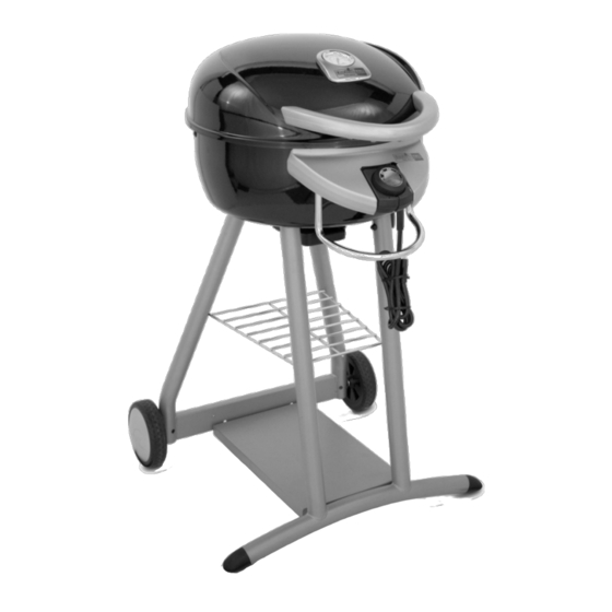
Char-Broil Patio Bistro Assembly Manual
Tru infrared
Hide thumbs
Also See for Patio Bistro:
- Manual (26 pages) ,
- Product manual (16 pages) ,
- Product manual (7 pages)

Related Manuals for Char-Broil Patio Bistro


Summary of Contents for Char-Broil Patio Bistro
- Page 1 Assembly Guide Model Numbers: 12601559-A1 12601578-A1 12601688-A1 ELECTRIC (English) 42805060 • 12/04/12...
-
Page 2: Assembly Guide
A, B, C, Assembly: ASSEMBLY GUIDE CAUTION: For your safety, before operating, Read Product Guide & Outdoor Cooking Guide provided with this grill. *SAFETY First….. Grill components may have sharp edges. Be careful when handling grill parts during assembly. We suggest that you wear a sturdy pair of leather gloves while handling the grill parts. BEFORE You begin assembly of your grill…. -
Page 3: Grill Parts Diagram
Grill Parts Diagram ASSEMBLY GUIDE Key Qty Description Key Qty Description Key Qty Description GREASE TRAY GUIDE GRILL LID GREASE TRAY HUBCAP LOWER BODY SMOKING RACK, ELECTRIC BISTRO WARMING RACK CONTROLLER NOT Pictured AXLE ELEMENT ASSEMBLY … GRILL COVER, ELECTRIC BISTRO HEAT INDICATOR WIRE SHELF …... -
Page 4: Grill Cart Assembly
GRILL CART Assembly ASSEMBLY GUIDE Fasteners Part – Rear Leg Set – Wheels – Hubcap Wheel Retaining Clip 3/8-16 Nut (qty 2) (qty 2) Step 1 – Attach 2 Axle Bolts to the Rear Leg Set (A1), thread a 3/8-16 nut as shown and tighten securely using a Axle Bolt small adjustable wrench. - Page 5 GRILL CART Assembly ASSEMBLY GUIDE Fasteners Part – Cart Base – Front Leg Set – Leg End Cap #10x3/8" 1/4-20x1/2" screw screw (qty 2) (qty 4) Step 2 – Attach Rear Leg Set (A1) to the Cart Base (A4) using 2 1/4-20 screws. Attach Front Leg Set (A5) to the Cart Base (A4) in the same manner, using 2 1/4-20 screws.
- Page 6 GRILL CART Assembly ASSEMBLY GUIDE Fasteners Part – Cart Bracket Wire Shelf – 1/4-20x2" screw (qty 4) 1/4-20 Nut 1/4-20 Nut (qty 4) Step 3 - Spread the leg assemblies apart just far enough to allow the insertion of the Wire Shelf (A8) into the 4 leg holes.
-
Page 7: Grill Body Assembly
GRILL BODY Assembly ASSEMBLY GUIDE Fasteners Part Qty. – Lower Body – Wind Shield 10-24x3/8" screw – Grill Lid (qty 3) 10-24 Nut Fiber Washer 1/4-20 Nut 1/4-20x3/4" (qty 10) (qty 5) (qty 2) screw (qty 2) Step 1 ASSEMBLY - Attach the Lower Body Assembly (B1) to the Cart Assembly by aligning the studs on the bottom of the Step 2... - Page 8 GRILL FINAL Assembly ASSEMBLY GUIDE NOTE: The Cooking Grate may Part Qty. have sharp edges. Be very careful Cooking Grate C1 – when handling the Cooking Grate. C2 – Warming Rack You should wear gloves when C3 – Smoking rack handling the Cooking Grate.
- Page 9 GRILL FINAL Assembly ASSEMBLY GUIDE Part Qty. C4 – Grease tray Step 3 - Install the Grease Tray (C4) by sliding the tray onto the Grease Tray Rails from the rear of the grill. Note: The grease tray rests between the grease tray rail stops. See detail shown in Figure A. Fig.
- Page 10 GRILL FINAL Assembly ASSEMBLY GUIDE Part Qty. Fasteners C5 – Controller C6 – Lid Handle 10-24x3/8" screw Fiber Washer (qty 2) (qty 2) NOTE: Be sure to press the controller into the receptacle as far as it will go. Route the controller cord BEHIND the towel bar as shown.
- Page 11 NOTES ASSEMBLY GUIDE...
- Page 12 THANK YOU FOR YOUR RECENT PURCHASE FROM CHECK OUT THESE GREAT FEATURES ON OUR WEBSITE Valuable product information • Inspiring grilling accessories • Reliable customer support • Delicious recipes and tips from chefs • Exciting events and promotions • And much more! •...