Table of Contents
Advertisement
Quick Links
Download this manual
See also:
Technical Manual
Intel® Server System H2000JF & H2000WP
Intel® Server System H2000JF & H2000WP
Quick Installation User's Guide
Quick Installation User's Guide
Thank you for buying an Intel® Server System. The following information will help you
assemble your Intel ® Server System and install components.
If you are not familiar with ESD [Electrostatic Discharge] procedures used during
system integration, see the complete ESD procedures described in your Service Guide.
This guide and other supporting documents are located on the web at:
http://www.intel.com/support.
*
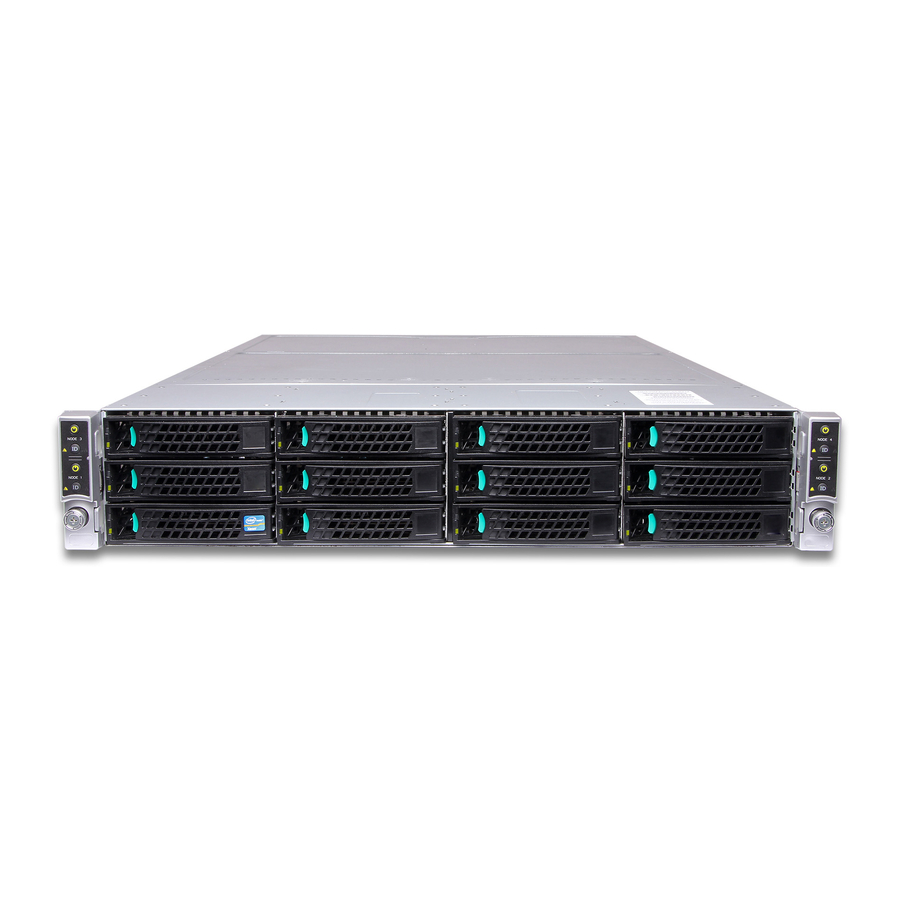
12 x 3.5" hard drive bay system as shown
G54451-002
Advertisement
Table of Contents

Related Manuals for Intel H2000WP


Summary of Contents for Intel H2000WP
- Page 1 Quick Installation User's Guide Quick Installation User's Guide Thank you for buying an Intel® Server System. The following information will help you assemble your Intel ® Server System and install components. If you are not familiar with ESD [Electrostatic Discharge] procedures used during system integration, see the complete ESD procedures described in your Service Guide.
- Page 2 ( This page is intentionally left blank. )
-
Page 3: Table Of Contents
Front Panel Controls and Indicators ................ 13 Cable Routing inside Server System H2000JF Node Tray........13 Optional Accessories ......................13 Cable Routing inside Server System H2000WP Node Tray ........14 Optional Accessories ......................14 Intel® Server System RAID Options ................ 14... - Page 4 Intel is a registered trademark of Intel Corporation or its subsidiaries in the United States and other countries. *Other names and brands may be claimed as the property of others. Copyright © 2012, Intel Corporation. All rights reserved.
- Page 5 Intel is a registered trademark of Intel Corporation or its subsidiaries in the United States and other countries. *Other names and brands may be claimed as the property of others. Copyright © 2012, Intel Corporation. All rights reserved.
-
Page 6: System Overview (Intel® Server System H2000Jf Family)
System Overview Intel® Server System H2000JF Family System Features and Components Common Compute Upper/Lower Redundant Node 3 Tray Power Distribution Power Supply Boards Compute Node 1 Tray HDD bays with Hot Swap Backplane Compute Node 4 Tray Compute Front Control Panel Node 2 Tray * 3.5"... -
Page 7: System Overview (Intel® Server System H2000Wp Family)
Node 4 Tray Compute Node 2 Tray Front Control Panel * 3.5" Hard Drive Bay system as shown Intel® Server System H2000JF and H2000WP Hard Drive Numbering Diagram 12X3.5” Hard Drive Bay Option - Front View Node3/HDD0 Node3/HDD1 Node3/HDD1 Node4/HDD0... -
Page 8: General Installation Process
General Installation Process The installation instructions in this section are for common components of Intel® Server System H2000JP and H2000WP family. Minimum Hardware Requirements Preparing the System To avoid integration difficulties and possible board damage, your system must meet the following minimum requirements: Observe normal ESD (Electrostatic Discharge) •... -
Page 9: Install/Remove Node Tray Air Duct
General Installation Process The installation instructions in this section are for common components of Intel® Server System H2000JP and H2000WP family. Remove/Install Node Tray Air Duct Removing the Air Duct Press and hold both left and right side of rear air duct (see letter “A”). -
Page 10: Install The Processor(S)
General Installation Process Install the Processor(s) A. Open the Socket Lever B. Open the Load Plate Push down the lever handle on the OPEN 1st side and Press the locking lever slightly to raise the away from the socket to release it. load plate . -
Page 11: Install Processor Heatsink(S)
Server Deployment Toolkit CD that accompanied your Intel Server Board ® ® S2600WP, or go to http://www.intel.com/support/motherboards/server/. (post-production) Memory sizing and configuration is supported only for qualified DIMMs approved by Intel. For a list of supported memory, see the tested memory list at http://www.intel.com/support/motherboards/server/. (post-production) -
Page 12: Install/Remove The Front Bezel
General Installation Process Install Memory Modules ... Continued To Install DIMMs: CAUTION: Avoid touching contacts Open both DIMM socket levers. when handling or installing DIMMs. Note location of alignment notch. Insert DIMM making sure the connector edge of the DIMM aligns correctly with the slot. Push down firmly on the DIMM until it snaps into place and both levers close. -
Page 13: Installing Pci Riser Assembly And Add-In Card On Riser Slot 1
General Installation Process Install Hard Drives ... Continued 3.5" Hard Drive Carrier (For system with 3.5" hard drive bay only) Remove the four screws securing the Remove the drive carrier by pressing the green button HDD interface bracket and remove the and opening the lever. -
Page 14: Install I/O Module Riser And Carrier Assembly On Riser Slot 2
(See letter “B”) I/O Connector Install Intel® RAID C600 Upgrade Key (optional) Locate the white 4-pin key header next to RISER SLOT_1. Carefully pickup the Intel ® RAID C600 Upgrade Key. Match the Key and connector orientation and press down to install. -
Page 15: Remove The Top Cover
Note: The FRUSDR utility must be run for full server configuration. B. Configure your RAID Controller: If using a RAID card, use the instructions provided with the RAID controller. If using on-board RAID, you must activate RAID in the BIOS setup. See the Intel Server Board ®... -
Page 16: Assembling The Server System With Server Chassis H2000
General Installation Process Intel® Server Chassis H2000 Assembly and Disassembly Assembling the Server System with Server Chassis H2000 A. Removing the Node Dummy Tray B. Inserting the Node Tray Node Dummy Tray Latch Always keep dummy trays in all empty node slots for thermal purpose. -
Page 17: Reference
Reference Intel® Server Board S2600JF Component Layout A. 2x7 fan control connector K. RMM4 lite U. NIC Port 1 B. VRS (4 total) L. POST and QSFP LED V. Riser Slot1 with PCIe Gen3 x16 C. Riser Slot3 with PCIe Gen3 x16 M. -
Page 18: Front Panel Controls And Indicators
Optional Accessories Product Code Description Intel Server Board S2600JF; Intel Node Power Board; Intel Bridge Board; 1U PCI Express Low Profile Riser; HNS2600JF 918336 1U Cu/Al 91mmx91mm Heat Sink; 1U Ex-Al 91mmx91mm Heat Sink; Three 4056 Dual Rotor Fan; Power Cable, Airduct;... -
Page 19: Cable Routing Inside Server System H2000Wp Node Tray
Fan control signal cable connection Optional Accessories Product Code Description Intel Server Board S2600WP; Intel Node Power Board; Intel Bridge Board; 1U PCI Express Low Profile 918378 Riser; 1U Cu/Al 84mmx106mm Heat Sink; 1U Ex-Al 84mmx106mm Heat Sink; Three 4056 Dual Rotor Fan; HNS2600WP Power Cable, Airduct;... -
Page 20: Intel® Server System Raid Options
Reference Intel® Sever System RAID Options Step 1 Step 2 Step 3 Step 4 Choose a RAID Choose Enable RAID Configure RAID proper Option hardware Option ® On-Server board AHCI Intel® RAID C600 1. During system post, press Intel RSTe: During system... - Page 22 G54451-002...