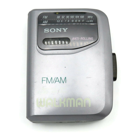
Sony Walkman WM-FX141 Service Manual
Radio cassette player
Hide thumbs
Also See for Walkman WM-FX141:
- Service manual (24 pages) ,
- Operating instructions (2 pages)
Table of Contents
Advertisement
QQ
3 7 63 1515 0
SERVICE MANUAL
Ver 1.3 1999. 05
With SUPPLEMENT-1 (9-923-296-81)
With SUPPLEMENT-2 (9-923-296-82)
TE
L 13942296513
Radio Frequency
FM : 87.6 – 108 MHz (US, Chilean, Latin America, Central and
: 65.0 – 107.9MHz (East European Model)
: 87.6 – 107.9 MHz (Other Models)
AM : 530 – 1,710 kHz (US, Chilean, Latin America, Central and
: 531 – 1,602kHz (Other Models)
Power requirements
3V DC batteries R6 (size AA) × 2
External DC 3V power sources
Battery life
(Aprroximate hours)
Battery
Sony alkaline LR6 (SG)
Sony R6P (SR)
www
.
MICROFILM
http://www.xiaoyu163.com
South America Models)
South America Models)
Playback
Radio
16 hrs
48 hrs
4.5 hrs
16 hrs
x
ao
u163
y
i
http://www.xiaoyu163.com
WM-FX141
2 9
8
Model Name Using Similar Mechanism
Tape Transport Mechanism Type
Q Q
3
6 7
1 3
1 5
SPECIFICATIONS
Dimensions
93.9 × 118.5 × 35.9 mm (w/h/d)
× 4
× 1
3
3
3
(3
/
/
4
4
Mass
205g (7.3 oz) incl.batteries
Supplied accessories
• Stereo headphones or earphones (1)
• Belt clip (1)
Design and specifications are subject to change without notice.
RADIO CASSETTE PLAYER
co
.
9 4
2 8
US Model
AEP Model
WM-FX101
MF-WMFX103-48
0 5
8
2 9
9 4
2 8
/
in.) incl. projecting parts
16
m
9 9
E Model
9 9
Advertisement
Table of Contents

Related Manuals for Sony Walkman WM-FX141


Summary of Contents for Sony Walkman WM-FX141
- Page 1 External DC 3V power sources Design and specifications are subject to change without notice. Battery life (Aprroximate hours) Battery Playback Radio Sony alkaline LR6 (SG) 16 hrs 48 hrs Sony R6P (SR) 4.5 hrs 16 hrs RADIO CASSETTE PLAYER u163 MICROFILM http://www.xiaoyu163.com...
-
Page 2: Table Of Contents
http://www.xiaoyu163.com TABLE OF CONTENTS 3 7 63 1515 0 1. GENERAL ·········································································· 3 2. DISASSEMBLY 2-1. Cabinet (Rear) ································································· 4 2-2. Mechanism Deck and Main Board ································· 4 2-3. Main Board ····································································· 5 2-4. Cassette Lid ····································································· 5 2-5. Dial Pointer Setting ························································· 5 3. -
Page 3: General
http://www.xiaoyu163.com SECTION 1 This section is extracted from instruction manual. GENERAL 3 7 63 1515 0 L 13942296513 u163 — 3 — http://www.xiaoyu163.com... -
Page 4: Disassembly
http://www.xiaoyu163.com SECTION 2 DISASSEMBLY 3 7 63 1515 0 Note : Disassemble the unit in the order as shown below. Cabinet (Rear) Mechanism deck and main board Main board Cassette lid Dial pointer setting Note : Follow the disassembly procedure in the numerical order given. 2-1. -
Page 5: Main Board
http://www.xiaoyu163.com 3 7 63 1515 0 2-3. MAIN BOARD 1 head flexible board 3 MAIN board 2 claws 2-4. CASSETTE LID Release the catch L 13942296513 Release the catch Front cabinet Cassette lid (Remove it in the direction of the arrow) 2-5. -
Page 6: Mechanical Adjustment
http://www.xiaoyu163.com SECTION 3 ADJUSTMENTS 3 7 63 1515 0 3-1. MECHANICAL ADJUSTMENTS 3-2. ELECTRICAL ADJUSTMENTS Precaution Precaution 1. Clean the following parts with a denatured-alcohol-moistend • Supplied voltage : 2.5V swab : • Switch and control position playback head pinch roller capstan rubber belts TAPE switch : NORM... - Page 7 http://www.xiaoyu163.com 3 7 63 1515 0 • Repeat the procedures in each adjustment several times for the 0 dB = 1 µV TUNER SECTION maximum level meter indication. • The frequency coverage and tracking adjustments should be [AM] finally done by the trimmer capacitors. BAND: AM Signal generator AM IF ADJUSTMENT...
- Page 8 http://www.xiaoyu163.com 3 7 63 1515 0 Adjustment Location : Main board antenna terminal L 13942296513 FM Frequency coverage AM IF Adjustment AM Frequency Adjustment AM Frequency coverage coverage Adjustment Adjustment AM Tracking Adjustment FM Frequency AM Tracking coverage Adjustment Adjustment FM Tracking FM Tracking Adjustment...
-
Page 9: Diagrams
http://www.xiaoyu163.com WM-FX141 SECTION 4 DIAGRAM 3 7 6 3 1 5 1 5 0 4-1. BLOCK DIAGRAM S303(2/2) DX → LOCAL E,MX,EE,AEP MODEL FM/AM,RF/AF AMP DET OUT MPX IN FM RF IN TRACKING L OUT AM RF IN FM MIX FM IF IN IC301 HP901... - Page 10 http://www.xiaoyu163.com WM-FX141 3 7 6 3 1 5 1 5 0 4-2. SCHEMATIC DIAGRAM — MAIN SECTION — E,MX,EE,AEP MODEL L3,CT3 L4,CT4 FM FREQ. COVER AM FREQ. COVER AM FERRITE-ROD ANTENNA LOCAL S303(2/2) CV1-4 TUNING L1,CT1 L2,CT2 FM TRACKING TRACKING US,5E,6E,8E MODEL AEP,E,MX,EE...
-
Page 11: Printed Wiring Board
http://www.xiaoyu163.com WM-FX141 4-3. PRINTED WIRING BOARD — MAIN SECTION — • Semiconductor Location Note: Ref. No. Location • X : parts extracted from the component side. • Y : parts extracted from the conductor side. IC301 • ® : Through hole. •... -
Page 12: Ic Block Diagram
http://www.xiaoyu163.com SECTION 5 SECTION 6 MAIN EXPLODED VIEWS ELECTRICAL PARTS LIST NOTE: NOTE: 4-4. IC BLOCK DIAGRAM 5-2. MECHANISM SECTION (MF-WMFX103-48) • -XX, -X mean standardized parts, so they may • The mechanical parts with no reference number • Abbreviation •... - Page 13 http://www.xiaoyu163.com MAIN 3 7 63 1515 0 Ref. No. Part No. Description Remarks Ref. No. Part No. Description Remarks < JUMPER CAPACITOR > R601 1-217-905-11 RES, CHIP 1/10W (EE, E, MX, AEP) 1-216-295-91 SHORT 0 (EE, E, MX, AEP) R602 1-216-309-00 METAL CHIP 1/10W 1-216-295-91 SHORT...
- Page 14 WM-FX141 3 7 63 1515 0 L 13942296513 u163 Sony Corporation 99D1644-1 Personal Audio Company 9-923-296-12 Printed in Japan © 1999.4 — 22 — Published by General Engineering Dept. http://www.xiaoyu163.com...
- Page 15 Chinese Model Page Part No. Description Remarks Part No. Description Remarks 3-860-407-42 MANUAL, INSTRUCTION 3-860-407-31 MANUAL, INSTRUCTION (ENGLISH, CHINESE) (SPANISH, PORTUGUESE) u163 Sony Corporation 98H16084-1D Printed in Japan ©1998.8 Personal A&V Products Company 9-923-296-81 Published by Quality Engineering Dept. (Shibaura) http://www.xiaoyu163.com...
- Page 16 http://www.xiaoyu163.com WM-FX141 3 7 63 1515 0 US Model E Model SERVICE MANUAL East European Model Chinese Model 1999. 05 SUPPLEMENT-2 File this supplement with the Service Manual. Subject : Main board modified (US model) NEW TYPE IDENTIFICATION L 13942296513 [MAIN BOARD] (Component Side) 1-673-769-12 u163...
- Page 17 http://www.xiaoyu163.com SECTION 1 ELECTRICAL ADJUSTMENT 3 7 63 1515 0 • US Model (Refer to pege 7) Adjustment Location : Main board 0 dB = 1 µV TUNER SECTION (Conductor side) • Repeat the procedures in each adjustment several times for the FM antenna terminal maximum level meter indication.
- Page 18 http://www.xiaoyu163.com WM-FX141 SECTION 2 DIAGRAMS Note on Schematic Diagram: Note on Printed Wiring Board: 2-1. BLOCK DIAGRAM 2-2. IC BLOCK DIAGRAM • All capacitors are in µF unless otherwise noted. pF: µµF • X : parts extracted from the component side. •...
- Page 19 http://www.xiaoyu163.com WM-FX141 2-3. PRINTED WIRING BOARD CV1-4 TUNING • Semiconductor w w w Location Ref. No. Location E-25 IC301 D-21 C-27 Q301 F-21 Q302 H-27 — 7 — — 8 — — 9 — — 10 — http://www.xiaoyu163.com...
- Page 20 http://www.xiaoyu163.com WM-FX141 3 7 6 3 1 5 1 5 0 2-4. SCHEMATIC DIAGRAM 1 3 9 4 2 2 9 6 5 1 3 w w w u 1 6 3 — 11 — — 12 — http://www.xiaoyu163.com...
-
Page 21: Electrical Parts List
1-419-158-11 COIL(WITH CORE) C306 1-124-434-00 ELECT 220uF 1-406-408-21 COIL(OSC) L101 1-500-245-11 INDUCTOR CHIP 0uH L201 1-500-245-11 INDUCTOR CHIP 0uH Sony Corporation L301 1-500-245-11 INDUCTOR CHIP 0uH 99E1618-1 Personal Audio Company 9-923-296-82 Printed in Japan ©1999.5 — 13 — — 14 —...