
Related Manuals for Martin Audio WLXGS


Summary of Contents for Martin Audio WLXGS
- Page 1 PREMININARY INFORMATION WLX, WLXGS User’s Guide The Martin Experience All material © 2007. Martin Audio Ltd. Subject to change without notice.
- Page 2 WLXGS (= WLX Groundstack). Standard WLX subwoofers may be flown from a standard W8LC grid via a single point W8LC lifting bar. W8LC Grid W8LC Lifting Bar All material © 2007. Martin Audio Ltd. Subject to change without notice.
-
Page 3: Specifications
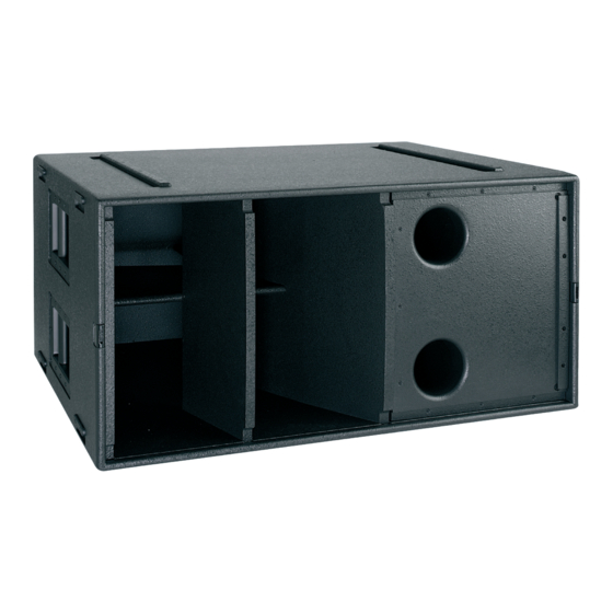
(W) 1002mm x (H) 490mm x (D) 800mm (950mm with wheelboard) (W) 39.45ins x (H) 19.3ins x (D) 31.5ins (37.4ins with wheelboard) Weight: 89 kg (196 lbs) All material © 2007. Martin Audio Ltd. Subject to change without notice. Application example... -
Page 4: Pin-Outs And Cabling
Pin-outs and cabling All material © 2007. Martin Audio Ltd. Subject to change without notice. Input Driver – (& link -1) Driver + (& link +1) Driver – (& link -2) Driver + (& link +2) link -3 link +3... - Page 5 Standardising on one good model of power amplifier (preferably the Martin Audio MA4.2S set to 32dB voltage gain and 0dB MLS) and correctly set-up controller (preferably the Martin Audio DX1 or the XTA DP226) will provide the most dynamic system performance and protection whilst simplifying design and reducing spares inventories.
-
Page 6: Crossover Frequencies
Time alignment W8L, W8LC and W8LM inter-driver delays Standard Martin Audio presets apply small output channel delays to DX1 or DP226 controllers to align the multiple drivers within W8L, W8LC and W8LM cabinets. These inter-driver delays are not user adjustable. They have a strong influence on a system’s off-axis lobe structure in addition to the usual on axis performance alignment. - Page 7 (Active mono - configured upper & lower for possible flown + stacked use) 6/8/12W8LM + WLX (Active mono) All material © 2007. Martin Audio Ltd. Subject to change without notice. Reference delay channels (left unlocked for main-to-subwoofers alignment) Reference delay channels (left...
- Page 8 The WLX sub-woofers signal will be on controller output channel 1 for standard W8LM set-ups. The WLX signal will be on channel 6 where a separate sub-woofer mix is to be used using a W8LM + WLX configuration. All material © 2007. Martin Audio Ltd. Subject to change without notice.
- Page 9 Sub-woofers may be flown above smaller main systems using W8L Series flying systems or adaptors. ViewPoint™ should be used to ensure system safety . . . 4 x WLX + 8 x W8LC mixed array for orchestral applications All material © 2007. Martin Audio Ltd. Subject to change without notice.
- Page 10 Connector Brackets – ViewPoint™ Rigging View Stacked WLXs or WLXGSs WLX or WLXGS subwoofers may be ground stacked below the main system. Ground stacked subwoofers can be up to 6dB more efficient than flown systems – assuming an acoustically solid floor - thanks to half spaced boundary conditions.
- Page 11 In the following example, aligning for maximum impact at the mix position will compromise bleacher impact and vice versa. All material © 2007. Martin Audio Ltd. Subject to change without notice.
- Page 12 - with suitably set controller limiters - but further, long-term increases caused by over- sized amplifiers should be avoided. Martin Audio MA series power amplifiers have regulated rails so it is quite permissible to use slightly All material © 2007. Martin Audio Ltd. Subject to change without notice.
-
Page 13: Mains Safety
(assuming professional audio equipment is in use FOH). Level controls The front panel level controls should be turned down (fully counter clockwise) until FOH-to-Amp rack lines All material © 2007. Martin Audio Ltd. Subject to change without notice. - Page 14 As mentioned earlier, ground stacking WLX or WLXGS subwoofers will provide maximum efficiency but a solid floor is essential for good dynamics. WLX/WLXGS horns flare from the label end. They can be symmetrically coupled by placing them label-to- label. All material © 2007. Martin Audio Ltd. Subject to change without notice.
- Page 15 2-wide symmetrical columns of WLX/WLXGS may be horizontally arrayed to improve mid-bass coverage. Array shapes vs coverage WLX or WLXGS subwoofers may be stacked and arrayed in various configurations to increase sound pressure and tailor coverage. The sound pressure increase is intuitive but the significance of subwoofer array shapes and sizes is often overlooked.
- Page 16 Stacking safety! Stacked WLX or WLXGS subwoofers should always be blocked, strapped and anchored from above by a qualified rigger. All material © 2007. Martin Audio Ltd. Subject to change without notice. Approx Boost Horizontal (wrt single unit)
- Page 17 Arcsin means “the angle whose sin is ...” Flat fronted cluster coverage patterns will be confined to one main lobe whose mid-bass crossover directivity is proportional to the size of the cluster. All material © 2007. Martin Audio Ltd. Subject to change without notice.
- Page 18 Polar plots have been simplified in this article for clarity. Real-world off-axis lobe amplitudes and shapes would vary considerably depending on boundary loading, echoes, reverberation and other audio sources affecting the same space. Vertical -6dB coverage The following table gives the approximate vertical coverage angles of typical WLX/WLXGS arrays - ignoring boundary effects (see later). WLX/WLXGS High Use tall stacks for long shots.
- Page 19 For instance, an 8 high ground-based stack of WLX/WLXGS subwoofers will act like the top half of a 16 high stack. It is possible to reach higher seating areas whilst retaining a tall vertical stack by electronically “tilting” the system - see later.
- Page 20 Spacing It is possible to space out WLX or WLXGS subwoofers to provide a larger frontal area with fewer units but care must be taken to avoid irregular coverage at higher, mid-bass frequencies. The following formula gives the pressure ratio p(h) (wrt to the on-axis pressure) for any off-axis angle of a regularly spaced linear array: All material ©...
- Page 21 - see the 2½ wavelength example above. An even number of half wavelengths will cause lobes along the line of the loudspeakers - see the 2 wavelength example below. The following tables give the maximum recommended gap (between WLX/WLXGS sides) for the relevant frequency range. 0.0m 0.5m...
- Page 22 Horizontal splays Splaying WLX/WLXGS arrays horizontally will widen their mid-bass coverage. The following sketch shows an 8 wide x 3 high WLX/WLXGS array arranged in four symmetrical pairs for smooth mid-bass coverage. WLX/WLXGS Wide (Splayed with Radius = width) Note that lower frequencies remain focussed when large arrays are used with large radii. Smaller systems with small radii will widen coverage at all frequencies but may cause cause low frequency build-up on thrust and island stages.
- Page 23 Stacked WLX/WLXGS application examples The following sketches show how WLX/WLXGS arrays may be deployed for a wide range of productions and types of venue. All productions and venues present their own unique requirements and these examples are intended as a template or starting point for your own specific design.
- Page 24 (3) WLX/WLXGS set-up for very high power dance/rock production in narrow arena Gives narrow horizontal & vertical coverage up to 120Hz - allowing for ground effects. Example 3 shows a very high power dance or rock set-up for a narrow “shoe box” venue. Note the four-wide left and right WLX arrays for tight horizontal control and the more tightly packed apron systems for central focusing.
- Page 25 Gives medium vertical & wide horizontal coverage up to 120Hz for audience on 3 sides - allowing for ground effects. Again, left and right WLX/WLXGS arrays (but this time at front and rear) are augmented by apron fills. The system set-ups may be thought of as three-sided versions of examples 3 and 5.
- Page 26 The following illustration shows what will happen. The direct signal will combine with the reflected signal as if it were a phantom source in the position shown. All material © 2007. Martin Audio Ltd. Subject to change without notice.
-
Page 27: Addition & Subtraction
The above shows how two pairs of sine waves (with identical amplitude and frequency characteristics) will sum. Pair (a) are in phase and add. Pair (b) are out of phase and cancel. All material © 2007. Martin Audio Ltd. Subject to change without notice. - Page 28 At this frequency the central position remains well covered but the polar pattern has changed dramatically around the sides. There are now strong lobes at the sides because the spacing is now an even number of half- wavelengths at this particular frequency. All material © 2007. Martin Audio Ltd. Subject to change without notice.
- Page 29 Again, the central response is maintained but there is a dip in response over wide areas either side of the centre. The spacing is an even number of half-wavelengths again so we see side lobes again. All material © 2007. Martin Audio Ltd. Subject to change without notice. 60Hz...
- Page 30 (in line with the subwoofers at 90º) will hear less of the fundamental but more of the harmonics whose full wavelengths coincide with the subwoofer spacing. All material © 2007. Martin Audio Ltd. Subject to change without notice.
-
Page 31: Important Note
**Important Note: The staggered stack (shown greyed out) illustrates the effect of electronic steering. For safety reasons, never try to tilt or stagger a real subwoofer stack. All material © 2007. Martin Audio Ltd. Subject to change without notice. - Page 32 The WLXs are 490mm wide giving a centre-to-centre spacing of 0.49m. This means that our delay increment (in ms) All material © 2007. Martin Audio Ltd. Subject to change without notice. = tan 30º x 0.49 x 1000 = 0.577 x 0.49 x 2.94...
-
Page 33: Going Further
The following illustration shows an example of a flat-fronted horizontal array electronically splayed to emulate the grey-out example shown. All material © 2007. Martin Audio Ltd. Subject to change without notice.