Table of Contents
Advertisement
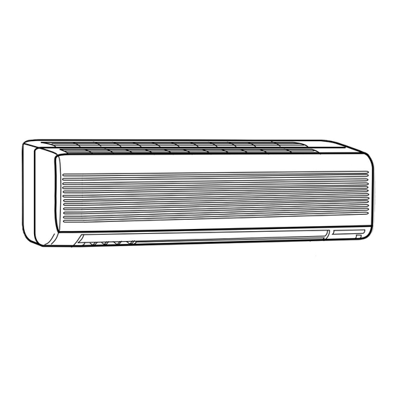
SPLIT-TYPE, HEAT PUMP AIR CONDITIONERS
SERVICE MANUAL
Wireless type
Models
MSH-A18WV -
MSH-A24WV -
MSH-A30WV -
Indication of model name
MSH-A18WV -
MSH-A24WV -
MSH-A30WV -
NOTE:
This service manual describes technical data of the indoor unit.
•Refer to the service manual OB322 when MSH-A18WV-
connected with MUH-A18WV-
•Refer to the service manual OB319 when MSH-A18WV-
MXZ-A26WV-
or MXZ-A32WV-
E1
•Refer to the service manual OB319 when MSH-A24WV-
MXZ-A32WV-
as multi system units.
E1
E1
E1
E1
E1
E1
E1
E1
, MUH-A24WV-
or MUH-A30WV-
E1
E1
E1
as multi system units.
E1
E1
( WH )
( WH )
( WH )
CONTENTS
1. TECHNICAL CHANGES ····································2
2. PART NAMES AND FUNCTIONS······················2
3. SPECIFICATION·················································4
4. NOISE CRITERIA CURVES ·······························5
5. OUTLINES AND DIMENSIONS ·························6
6. WIRING DIAGRAM ············································7
7. REFRIGERANT SYSTEM DIAGRAM ················8
8. MICROPROCESSOR CONTROL ······················9
9. SERVICE FUNCTIONS ····································18
10. TROUBLESHOOTING······································20
11. DISASSEMBLY INSTRUCTIONS·····················28
12. PARTS LIST······················································30
13. OPTIONAL PARTS ······················BACK COVER
, MSH-A24WV-
or MSH-A30WV-
E1
.
E1
is connected with MXZ-A18WV-
is connected with MXZ-A26WV-
No. OB321
is
E1
,
E1
or
E1
Advertisement
Table of Contents

Related Manuals for Mitsubishi MSH-A18WV


Summary of Contents for Mitsubishi MSH-A18WV
-
Page 1: Table Of Contents
MSH-A30WV - 12. PARTS LIST······················································30 13. OPTIONAL PARTS ······················BACK COVER NOTE: This service manual describes technical data of the indoor unit. •Refer to the service manual OB322 when MSH-A18WV- , MSH-A24WV- or MSH-A30WV- connected with MUH-A18WV- , MUH-A24WV- or MUH-A30WV- •Refer to the service manual OB319 when MSH-A18WV-... -
Page 2: Technical Changes
TECHNICAL CHANGES MSH-18RV - MSH-A18WV - 1. Indoor unit model has changed. 2. Rated voltage has changed. (220V-240V 230V) 3. Remote controller has changed. •LONG MODE and WIDE MODE have been added. 4. Indoor fan motor has changed.(RA4V27-EF RC4V32-AA) 5. Indoor heat exchanger has changed. - Page 3 REMOTE CONTROLLER MSH-A18WV - MSH-A24WV - MSH-A30WV - Signal transmitting section Operation display section OPERATE /STOP (ON /OFF)button ON/OFF WARM COOL TEMPERATURE buttons Indication of remote controller model is on back. Open the front lid. CLOCK ON/OFF WARM COOL VANE button...
-
Page 4: Specification
SPECIFICATION •Refer to the service manual OB322 when MSH-A18WV- , MSH-A24WV- or MSH-A30WV- is connected with MUH-A18WV- , MUH-A24WV- or MUH-A30WV- •Refer to the service manual OB319 when MSH-A18WV- is connected with MXZ-A18WV- , MXZ-A26WV- MXZ-A32WV- as multi system units. -
Page 5: Noise Criteria Curves
NOISE CRITERIA CURVES MSH-A18WV- MSH-A24WV- FAN SPEED SPL(dB(A)) LINE FAN SPEED SPL(dB(A)) LINE High High Test conditions, Test conditions, Cooling : Dry-bulb temperature 27: Wet-bulb temperature 19: Cooling : Dry-bulb temperature 27: Wet-bulb temperature 19: Heating : Dry-bulb temperature 20: Wet-bulb temperature 15.5: Heating : Dry-bulb temperature 20: Wet-bulb temperature 15.5:... -
Page 6: Outlines And Dimensions
OUTLINES AND DIMENSIONS MSH-A18WV - Unit: mm MSH-A24WV - MSH-A30WV - INDOOR UNIT Installation plate Indoor unit 1068 414.5 414.5 Wall hole [ 75 1100 Liquid line [ 6.35- 0.5m Installation plate Gas line [ 12-0.43m Insulation [ 50 O.D [ 32 I.D... -
Page 7: Wiring Diagram
WIRING DIAGRAM MSH-A18WV - MSH-A24WV - MODELS WIRING DIAGRAM INDOOR UNIT HIC1 TO OUTDOOR RT12 UNIT CONNECTING CN112 CN201 NR11 TRANS SR141 TAB12 POWER SUPPLY CN211 CORD ELECTRONIC CONTROL ~/N 230V RT11 P.C. BOARD 50Hz DISPLAY RECEIVER CIRCUIT BREAKER P.C.BOARD P.C.BOARD... -
Page 8: Refrigerant System Diagram
REFRIGERANT SYSTEM DIAGRAM MSH-A18WV - MSH-A24WV - Unit:mm INDOOR UNIT INDOOR UNIT Refrigerant pipe [15.88 Refrigerant pipe [12.7 (with heat insulator) (with heat insulator) Indoor coil Indoor coil thermistor Indoor Indoor thermistor RT12 RT12 heat heat exchanger exchanger Distributor Distributor... -
Page 9: Microprocessor Control
MICROPROCESSOR CONTROL MSH-A18WV - MSH-A24WV - MSH-A30WV - WIRELESS REMOTE CONTROLLER Signal transmitting section Operation display section OPERATE /STOP (ON /OFF)button ON/OFF WARM COOL TEMPERATURE buttons CLOCK ON/OFF WARM COOL VANE button FAN SPEED CONTROL button STOP (Horizontal vane button) - Page 10 • Once the mode is fixed, the mode does not change by room temperature afterwards. • Under the ON-TIMER ( ) operation, mode is determined according to the room temperature at the set time the operation starts. • When the system is stopped on the remote controller, and restarted within 2 hours in “I FEEL CONTROL” ( ) mode, the system operates in previous mode automatically regardless of the room temperature.
- Page 11 The indoor fan operates at the set speed and the compressor stops for 5 minutes. After that, if RT12 still reads below 3°C(MSH-A18WV)/ 0°C(MSH-A24WV)/ RT12 or RT13 still reads below 1°C (MSH- A30WV) this mode prolonged until the RT12 reads over 3°C(MSH-A18WV)/ 0°C(MSH-A24WV) / RT12 or RT13 still reads over 1°C(MSH-A30WV).
- Page 12 Operation time chart Example Thermostat Indoor fan Outdoor fan Compressor 8 min. 1 min. 3 min. 4 min. 3. Coil frost prevention • The operation is as same as coil frost prevention during COOL mode of “I FEEL CONTROL”. • Indoor fan operates at the set speed and the compressor stops for 5 minutes, because protection(Coil frost prevention) has the priority.
- Page 13 8-2. COOL ( ) OPERATION (1) Press OPERATE/STOP (ON/OFF) button. OPERATION INDICATOR lamp of the indoor unit turns on with a beep tone. (2) Select COOL mode with the OPERATION SELECT button. (3) Press the TEMPERATURE buttons. (TOO WARM or TOO COOL button) to select the desired temperature.
- Page 14 8-6. AUTO VANE OPERATION 1. Horizontal vane (1) Vane motor drive These models are equipped with a stepping motor for the horizontal vane. The rotating direction, speed, and angle of the motor are controlled by pulse signals (approx. 12V) transmitted from indoor microprocessor. (2) The horizontal vane angle and mode changes as follows by pressing the VANE button.
- Page 15 (9) ECONO COOL ( ) operation (ECONOmical operation) When the ECONO COOL button is pressed in COOL mode, set temperature is automatically set 2°C higher than that in COOL mode. Also the horizontal vane swings in various cycle according to the temperature of indoor heat exchanger(Tp (w 1) SWING operation makes you feel cooler than set temperature.
- Page 16 2. Vertical vane (1) Vane motor drive These models are equipped with a stepping motor for the vertical vane. The rotating direction, speed, and angle of the motor are controlled by pulse signals (approx. 12V) transmitted from microprocessor. (2) The vertical vane angle and mode change as follows by pressing the WIDE VANE button. SWING (3) Positioning The vane is once pressed to the vane stopper to confirm the standard position and then set to the desired angle.
- Page 17 2. Cancel TIMER setting can be cancelled with the ON/OFF TIMER buttons. To cancel the ON timer, press the “ON-TIMER” button. To cancel the OFF timer, press the “OFF-TIMER” button. TIMER is cancelled and the display of set time disappears. PROGRAM TIMER •...
-
Page 18: Service Functions
SERVICE FUNCTIONS MSH-A18WV - MSH-A24WV - MSH-A30WV - 9-1. TIMER SHORT MODE For service, set time can be shortened by short circuit of JPG and JPS on the electronic control P.C. board. The time will be shortened as follows. Set time : 1 minute... - Page 19 How to release “AUTO RESTART FUNCTION” Turn off the main power for the unit. Pull out the electronic control P.C. board, the receiver P.C. board and the display P.C.board. (Refer to page 27.) Solder jumper wire to the RESISTOR JR07 on the indoor electronic control P.C.
-
Page 20: Troubleshooting
TROUBLESHOOTING MSH-A18WV - MSH-A24WV - MSH-A30WV - 10-1. Cautions on troubleshooting 1. Before troubleshooting, check the following: (1) Check the power supply voltage. (2) Check the indoor/outdoor connecting wire for mis-wiring. 2. Take care the following during servicing. (1) Before servicing the air conditioner, be sure to first turn off the remote controller to stop the main unit, and then after confirming the horizontal vane is closed, turn off the breaker and / or disconnect the power plug. - Page 21 10-2. Instruction of troubleshooting Start Indoor unit Indoor unit Indoor unit operates. OPERATION INDICATOR operates. doesn't receive Outdoor unit lamp on the indoor unit is Outdoor unit the signal from doesn't operate flashing on and off. doesn't remote controller. normally. operate.
- Page 22 1. Troubleshooting check table • The following indication applies regardless of shape of the indicator. flashing · Flashing of the OPERATION INDICATOR lamp (on the left-hand side) indicates possible Operation Indicator abnormalities. · The OPERATION INDICATOR lamp (on the left-hand side) is lighting during normal operation. Before taking measures, make sure that the symptom reappears, for accurate troubleshooting.
- Page 23 2. Trouble criterion of main parts MSH-A18WV - MSH-A24WV - MSH-A30WV - Part name Check method and criterion Figure Measure the resistance with a tester. Room temperature (Part temperature 10˚C ~ 30˚C) thermistor(RT11) Normal Abnormal Indoor coil thermistor Open or short-circuit (RT12(main), RT13(sub)) 8 k"...
-
Page 24: Check Of Indoor Fan Motor
When OPERATION INDICATOR lamp flashes 3-time. Indoor fan motor doesn’t operate. Check of indoor fan motor Turn OFF the power supply. Check connector CN211 visually. Is soldered point of the connector Are lead wires connected? Resolder it. correctly soldered? Reconnect the lead wires. Disconnect lead wires from connector CN211 on the indoor electronic control P.C. -
Page 25: Check Of Indoor Electronic Control P.c. Board
The unit doesn’t operate with the remote controller. Also, the OPERATION INDICATOR lamp doesn’t light up by press- ing the EMERGENCY OPERATION switch. Check of indoor electronic control P.C. board Check the both “parts side” and “pattern Varistor (NR11) side” of indoor electronic control P.C. board visually. -
Page 26: How To Check Mis-Wiring
When OPERATION INDICATOR lamp flashes ON and OFF in every 0.5-second. Outdoor unit doesn’t operate. How to check mis-wiring w Short circuit of JPG and JPS on the indoor electronic control P.C. board enables self -check to be displayed in 3 seconds. Start •... - Page 27 TEST POINT DIAGRAM AND VOLTAGE MSH-A18WV - MSH-A24WV - MSH-A30WV - Indoor electronic control P.C. board Fan motor power supply Power supply input 230V AC 5V DC Fuse (F11) 250V AC 3.15A Room temperature ther- mistor(RT11) R132 Indoor coil thermistor(RT12(main))
-
Page 28: Disassembly Instructions
1Hold the sleeve, and 2Pull the terminal while pull out the terminal pushing the locking slowly. Locking lever lever. Connector MSH-A18WV - MSH-A24WV - MSH-A30WV - INDOOR UNIT OPERATING PROCEDURE PHOTOS 1. Removing the front panel Photo 1 (1) Remove the screw caps of the front panel. - Page 29 OPERATING PROCEDURE PHOTOS Photo 3 3. Removing the electrical box Screws of the ground wire (1) Remove the front panel. (Refer to 1.) (2) Remove the electrical cover. (Refer to 2.) (3) Disconnect the connector of the indoor coil thermistor. (4) Disconnect the motor connector (CN211 and CN121) and the vane motor connector (CN151) on the electronic control P.C.
-
Page 30: Parts List
PARTS LIST MSH-A18WV - (WH) MSH-A24WV - (WH) MSH-A30WV - (WH) 12-1. INDOOR UNIT STRUCTURAL PARTS 12-2. INDOOR UNIT HEAT EXCHANGER CATCH Optional parts SCREW (See back cover.) 12-1. INDOOR UNIT STRUCTURAL PARTS Part number that is circled is not shown in the illustration. - Page 31 MSH-A18WV - (WH) MSH-A24WV - (WH) MSH-A30WV - (WH) 12-4. ACCESSORY AND 12-3. INDOOR UNIT FUNCTIONAL PARTS AND REMOTE CONTROLLER ELECTRICAL PARTS SLEEVE BEARING ROOM TEMPERATURE THERMISTOR 15 16 VARISTOR FUSE 12-3. INDOOR UNIT FUNCTIONAL PARTS AND ELECTRICAL PARTS Part numbers that are circled are not shown in the illustration.
-
Page 32: Optional Parts
MSH-A24WV- MAC-1700FT MSH-A30WV- Air cleanig filter (White bellows type) HEAD OFFICE: MITSUBISHI DENKI BLDG.,2-2-3, MARUNOUCHI, CHIYODA-KU, TOKYO100-8310, JAPAN C C Copyright 2003 MITSUBISHI ELECTRIC ENGINEERING CO.,LTD New publication, effective Nov. 2003 Distributed in Nov. 2003. No.OB321 6 Specifications subject to change without notice.