Table of Contents
Advertisement
Advertisement
Table of Contents

Related Manuals for Mark Levinson N 320S


Summary of Contents for Mark Levinson N 320S
- Page 1 Owner’ s Manual Nº 320S Preamplifier...
-
Page 2: Important Safety Instructions
Important Safety Instructions Read all instructions and precautions carefully and completely before attempting to operate this component. NEVER clean or make/break connections to this component unless it and all associated components are powered off and disconnected from electrical outlets. ALWAYS terminate this connection with a three-conductor AC power cord that includes an earth-ground connection. - Page 3 Connect the component to an electrical outlet on a circuit different from that to which the receiver is connected. • Consult an authorized Mark Levinson dealer or an experienced radio/television technician for assistance. CAUTION • DO NOT ATTEMPT TO REPAIR THIS PRODUCT. CONTACT AN AUTHORIZED MARK LEVINSON DEALER OR MARK LEVINSON CUSTOMER SUPPORT AT 781-280-0300 OR www.marklevinson.
-
Page 4: Table Of Contents
Teach IR Menu .......3-8 Setup Menu Parameters ..... . .3-11 Mute • MaxVol • Trig. • Sw Mark Levinson... - Page 5 Nº 320S Section 4: Controls & Modes Standby ........4-1 SLEEP Display Intensity .
-
Page 6: Documentation Conventions
Calls attention to a procedure, practice, condition, or the like that, if not correctly performed or adhered to, could result in damage or destruction to part or all of the component. Note Calls attention to information that is essential to highlight. Mark Levinson... -
Page 7: Section 1: Getting Started
Getting Started Special Design Features Thank you for purchasing the Nº 320S Preamplifier. A direct descendant of the Nº 32 Reference Preamplifier, the Nº 320S features audio circuits, controls, architecture, and optional phono modules based on the critically acclaimed Nº32. In fact, some audio circuits, such as the proprietary discrete volume attenuators, are identical to those found in the Nº... - Page 8 Two Link communication ports make it possible to link the Nº 320S to compatible Mark Levinson components, while a trigger output connector, ir input connector, and RS-232 port offer even more control possibilities.
- Page 9 Following the Mark Levinson tradition, the Nº 320S exceeds all reasonable expectations for a stereo preamplifier. Its flexible design – including seven configurable inputs, separate main and record output connectors, and complete surround sound processor integration –...
-
Page 10: Installation Considerations
• inspect the Nº 320S for signs of damage during shipment. If damage is discovered, contact an authorized Mark Levinson dealer for assistance making appropriate claims. • locate and remove the accessory box from the carton. - Page 11 Nº 320S Placement Item Detachable AC power cord Link communication cable 1/8-inch hex key Phillips-head screwdriver (size 1) Nº 320S remote control White gloves (pair)** Warranty & Product Registration Card The remote control comes with two AAA batteries, which should be replaced as needed. ** The white gloves are provided to assist with the initial unpacking and installation of the Nº...
- Page 12 These screws are identified in the illustration to the left. 3. Remove the battery compartment cover from the remote control. 4. Remove the old batteries inserted in the battery compartment (if applicable). Mark Levinson...
-
Page 13: Power Requirements
CAUTION • DO NOT ATTEMPT TO ADJUST THE OPERATING VOLTAGE. CONSULT AN AUTHORIZED MARK LEVINSON DEALER IF THE OPERATING VOLTAGE IS INCORRECT OR IF THE OPERATING VOLTAGE MUST BE CHANGED FOR RELOCATION PURPOSES. •... -
Page 14: Quick Start Guide
Nº 320S. However, it is important to read this owner’s manual before attempting more extensive use. This owner’s manual contains information about features that enhance operation and performance, as well as important safety, installation, and operation instructions designed to prevent personal injuries as well as product damage. Mark Levinson... - Page 15 Nº 320S CAUTION NEVER MAKE OR BREAK CONNECTIONS TO THE Nº 320S UNLESS IT AND ALL ASSOCIATED COMPONENTS ARE POWERED OFF AND DISCONNECTED FROM ELECTRICAL OUTLETS. To begin using the Nº 320S: 1. Make sure the Nº 320S and all associated components are powered off and disconnected from electrical outlets.
- Page 16 • Factory-default input names correspond to their assigned stereo input connectors. For instance, Input 1 is assigned to the stereo input connectors labeled 1, Input 2 is assigned to the stereo input connectors labeled 2, and so on. Mark Levinson...
-
Page 17: Section 2: Basic Operation
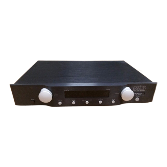
select power setup The numbers in the Nº 320S front panel illustration shown above correspond to the numbered items in the Front Panel Overview section that begins below. Basic Operation IR Receiver polarity enter display intensity balance Front Panel Overview Unless otherwise specified, the numbered items in this section indicate the commands the front panel performs during normal operating mode. - Page 18 Refer to Polarity (page 4-3) for additional information. 6. mono LED Lights red to indicate that mono playback has been activated with the remote control mono button. Refer to Mono Playback (page 4-5) for additional information. Mark Levinson...
- Page 19 Nº 320S 7. volume knob Adjusts master volume level. Rotating the volume knob increases (clockwise) and decreases (counterclockwise) master volume level in 1.0dB increments up to 23.0dB and in 0.1dB increments above 23.0dB. The minimum master volume level setting is OFF. The MaxVol parameter can be used to determine the maximum master volume level setting in 0.1dB increments between 40.0 and 80.0dB.
- Page 20 The mute level can be set in 0.1dB increments between –10.0 and –80.0dB. The factory-default mute level is –20.0dB. Note Rotating the front panel volume knob deactivates mute, adjusting master volume from the muted volume level. Mark Levinson...
-
Page 21: Rear Panel Overview
Nº 320S MARK LEVINSON record outputs RIGHT CHANNEL PREAMPLIFIER Nº 320S Made in the U.S.A. main outputs inputs The numbers in the Nº 320S rear panel illustration shown above correspond to the numbered items in the Rear Panel Overview section that begins below. - Page 22 Nº 320S balanced output connector pin assignments correspond to the associated power amplifier balanced input connector pin assignments. If not, wire the cable so that the appropriate input pin connects to the appropriate output pin. Mark Levinson...
- Page 23 Mark Levinson power amplifier that offers Link communication ports. The slave in communication port can be connected to a compatible Mark Levinson digital audio processor or digital transport that offers Link communication ports. Note Refer to Linking (page 2-9) BEFORE linking the Nº...
- Page 24 AMX™ and Crestron™ systems. One 6-pin modular RJ-11 port labeled RS-232 is available. 10. serial number label Indicates the Nº 320S serial number, which is required for product registration and warranty service. Mark Levinson...
-
Page 25: Linking
Link communication ports, including master, slave in, slave out, communication ports. These communication ports can be used to “link” compatible Mark Levinson components in a slave chain, allowing them to share controls such as display intensity, standby, playback, input selection, and record. - Page 26 8 are not used. When linking components with constructed Link communication cables, twist the cable 180˚ as shown in the illustration below for a straight-through (pin 1-to-pin 1) connection. Mark Levinson Digital Audio Processor or Transport 8-Pin RJ-45 Plug (Pin 1) Locking Tab 180˚...
- Page 27 Digital transports CANNOT be included in a slave chain that does not include a compatible Mark Levinson digital audio processor. • Connect multiple digital transports in a “daisy chain” using slave out-to-slave in communication port connections.
- Page 28 5. Play the input source on the digital transport selected in step 1 (if applicable). • All linked components should automatically come out of standby. • The linked digital audio processor and Nº 320S should automatically select the appropriate input. Mark Levinson...
-
Page 29: Link Controls
Nº432 Power Amplifier The last power amplifier control communication port is not connected. Linking Mark Levinson components allows them to share controls such as display intensity, standby, playback, input selection, and record. Note the following: • Linked components must be powered on ONE AT A TIME in the specific order listed in step 4 (page 2-12) to ensure proper functioning of Link controls. -
Page 30: Controls
Configuring the linked digital audio processor for an HDCD recording session automatically attenuates the linked Nº 320S master volume level the required –6dB. Mark Levinson Power Amplifier Placing a linked power amplifier into standby also places all other linked power amplifiers into standby. -
Page 31: Remote Control Overview
Nº 320S Operation Considerations Note The Nº 31, Nº 31.5, Nº 37, and Nº 39 remote controls can be used to control Nº 320S master volume level. This command is available over IR (not Link connections). Before using one of these remote controls to adjust Nº320S master volume level, make sure the digital transport setup menu volume control parameter is set to fixed. - Page 32 Refer to Operation Considerations (previous page) for additional information. enter volume – mute Mark Levinson 2. standby button Places the Nº 320S into standby and takes the Nº 320S out of standby, which allows the Nº 320S to remain warmed-up to deliver optimal performance at all times.
- Page 33 Nº 320S 4. enter button Selects and deselects menu items when the setup menu is open. The enter button performs no function during normal operation. 5. volume ± buttons Adjust master volume level. Pressing the volume ± buttons increases (+) and decreases (–) master volume level in 1.0dB increments up to 23.0dB and in 0.1dB increments above 23.0dB.
- Page 34 The front panel mute LED lights red to indicate that mute is activated. Pressing and releasing the mute button again restores master volume to its original level. Mark Levinson...
- Page 35 Nº 320S Basic Operation The Mute parameter can be used to determine the amount of master volume level attenuation that occurs when mute is activated. The mute level can be set in 0.1dB increments between –10.0 and –80.0dB. The factory-default mute level is –20.0dB.
-
Page 36: Section 3: Setup Menu
Setup Menu Navigating the Setup Menu The front panel and remote control setup buttons provide convenient access to the setup menu structure shown below, which can be used to configure the Nº 320S to suit individual preferences and listening spaces. The front panel display provides one-line viewing of the setup menu shown here, indicating the current menu item. - Page 37 Note When a parameter is deselected, the NO CHANGE message will appear on the front panel display as shown to the left if no changes have been made to the parameter’ s last stored setting. Mark Levinson...
-
Page 38: Volume Knob & ± Buttons
Nº 320S select knob & ± buttons volume knob & ± buttons Scroll through menu items. Rotating the select knob or pressing the select ± buttons scrolls upward (clockwise/+) and downward (counterclockwise/–) through all menu items available on the open menu. The front panel display indicates the current menu item. - Page 39 28 custom input names that can be used for the most common associated components, including other Mark Levinson components. It also includes custom input names that can be used to deactivate unused inputs or to activate SSP mode.
- Page 40 No30, No30.5, Identifies an input associated with the corresponding Mark No30.6, No35, Levinson component. Linked Mark Levinson components No36, No36S, must have recognizable custom input names to share Link No360, No360S, controls. For instance, an input associated with a Nº 360S No39, No390S Digital Audio Processor should be named Nº...
- Page 41 • Select this custom input name (if the custom names list option was selected in step 3). The SAVING DATA message will appear on the front panel display to indicate that the new input name is being saved. Mark Levinson...
- Page 42 Nº 320S Gain +0dB, +6dB, +12dB, +18dB Offset –20.0 to +20.0dB • Select this character (if the character list option was selected in step 3). The blinking cursor will advance to the next character space. Repeat steps 4 and 5 until all desired characters have been entered.
-
Page 43: Rec.out
Nº 320S IR commands to be sent from a learning remote control even if the Nº 320S remote control is not present. Mark Levinson... - Page 44 Nº 320S enter Command Description VOLUME UP Performs volume + button commands. VOLUME DOWN Performs volume – button commands. SELECT NEXT Performs select + button commands. SELECT PREV Performs select – button commands. INTENSITY KEY Performs display button commands. MUTE KEY Performs mute button commands.
- Page 45 Nº 320S master volume level. This command is available over IR (not Link connections). Before using one of these remote controls to adjust Nº320S master volume level, make sure the digital transport setup menu volume control parameter is set to fixed. Mark Levinson...
-
Page 46: Setup Menu Parameters
Nº 320S Mute –10.0 to –80.0dB MaxVol 40.0 to 80.0dB Trig. 12v,L; 5v,P Non-adjustable Setup Menu Parameters Default Parameter Setting Mute -20.0dB MaxVol 80.0dB Trig. 12v,L Determines the amount of master volume level attenuation that occurs when mute is activated with the front panel or remote control mute button. -
Page 47: Section 4: Controls & Modes
SLEEP -OFF-, 0h 30m to 4h 0m Controls & Modes Standby Allows the Nº 320S to remain warmed-up to deliver optimal performance at all times. The Nº 320S cannot be placed into standby unless it is powered on with the front panel power button. -
Page 48: Display Intensity
The factory-default illumination level is FULL (100%). When the OFF (0%) illumination level is selected: • The front panel display automatically activates whenever a change in status is detected. • The front panel standby LED lights at the FULL (100%) illumination level. Mark Levinson... -
Page 49: Polarity
Nº 320S To adjust display intensity: Press and release the front panel display intensity button or the remote control display button to cycle through the four available illumination levels. • Front panel display characters and the front panel standby LED automatically adjust to the selected illumination level. Polarity Controls the polarity of the main output signal, whether that signal is using the balanced (XLR) or single-ended (RCA) main... - Page 50 The front panel balance LED remains lit if the left-to-right channel balance of the main output connectors is offset. Note All Nº 320S volume controls, including master volume and balance, are deactivated when SSP mode (page 4-8) is activated. Mark Levinson...
-
Page 51: Mono Playback
Nº 320S MODE L + R, L ONLY, R ONLY, L – R MODE: L + R Mono Playback Sends mono (rather than stereo) signals to the main output connectors, whether those signals are using the balanced (XLR) or single-ended (RCA) main output connectors. The mono playback control has no affect on the record output connectors. - Page 52 The front panel balance LED lights red to indicate that the balance control is open. 7. Rotate the front panel volume knob or press the remote control volume ± buttons to center the image between the front left and right loudspeakers. Mark Levinson...
- Page 53 Nº 320S L – R Phono Alignment MODE: L + R MODE: L – R 8. When the desired adjustments have been made, press and release the balance button to close the balance control. • Otherwise, the balance control automatically closes a few seconds after the last command is received.
-
Page 54: Ssp (Surround Sound Processor) Mode
All Nº 320S volume controls – including master volume, balance, and volume-related parameters – are deactivated to prevent the Nº 320s from distorting channel balance. As a result, the processor controls the relative volume level of all channels while maintaining its calibrated output levels. Mark Levinson... - Page 55 Nº 320S To activate and use SSP mode: 1. Make sure the Nº 320S and all associated components are powered off and disconnected from electrical outlets. 2. Connect the output connectors on the surround sound source component to the input connectors on the surround sound processor.
- Page 56 10. Press the enter button to select the SSP name, which activates SSP mode. • The SAVING DATA message will appear on the front panel display as shown to the left to indicate that the SSP name is being saved. Mark Levinson...
-
Page 57: Section 5: Troubleshooting & Maintenance
Incorrect operation is sometimes mistaken for malfunction. If problems occur, refer to this section for troubleshooting information. If problems persist, contact Mark Levinson Customer Support at 781-280-0300 or www.marklevinson.com. 1. Examine the power cord to ensure that it is connected to both the ~ac mains connector and a wall outlet. - Page 58 Levinson dealer for assistance. 2. Disconnect components one at a time to isolate the problem. Once the problem is identified, make sure the problematic component is properly grounded and connected to the same electrical circuit as the Nº 320S. Mark Levinson...
- Page 59 1. Make sure the Name parameter for the selected input has not been set to unused. 1. Make sure the slave chain includes Mark Levinson components that are compatible with the Nº 320S. 2. Examine Link connections to ensure a solid connection between linked components.
-
Page 60: Restoring Factory-Default Settings
CANCELLED messages will blink on the front panel display as shown below to indicate that restoration of factory default settings has been cancelled. CLEAR 5. Power on all associated components that were powered off in step 1. Mark Levinson RESTORED CANCELLED... -
Page 61: Care & Maintenance
Nº 320S Care & Maintenance The Nº 320S requires routine care and maintenance to ensure optimal performance. The bulleted items below indicate maintenance procedures that should be performed on a regular basis. Note Failure to perform the maintenance procedures included in this section may void the manufacturer’... -
Page 62: Appendix
• 4 single-ended (Mark Levinson-RCA) stereo inputs • 1 balanced (male XLR) stereo main output • 1 single-ended (Mark Levinson-RCA) stereo main output • 2 single-ended (Mark Levinson-RCA) stereo record outputs • 2 8-pin RJ-45 connectors for Link communication •... - Page 63 <90dB (any input to any output, input terminated) • 20Hz to 20kHz (input terminated < -94dBV) • 10 to 40kHz, ±0.2 dB • 30 pounds (14kg) Specifications are subject to change without notice. Mark Levinson Connectors 0.8V 1.6V 3.3V 6.6V...
-
Page 64: Dimensions
Nº 320S Dimensions Front View 2.92” (74.04mm) power 2.07” (52.45mm) Top View 13.58” (344.91mm) 17.75” (450.85mm) polarity mono volume select setup enter display intensity balance mute 13.62” (345.95mm) 17.50” (444.50mm) Specifications are subject to change without notice. Appendix 2.66” PREAMPLIFIER Nº... -
Page 65: Installation Worksheet
Set Inputs Name Input 1 Input 2 Input 3 Input 4 Input 5 Input 6 Input 7 Setup Menu Parameters Mute Polarity MaxVol Intensity Trig. Balance Mono Playback Mark Levinson Gain Offset Rec.Out Control/Mode Settings Gain Offset Rec.Out Control/Mode Settings... -
Page 66: Index
SYMBOLS , iv, IFC , iv, IFC CAUTION, iv, 1-6, 1-7, 1-9, 2-5, 2-10, 3-5, 3-8, 4-9, 5-5, IFC , iv Note, iv, 1-5, 1-8, 1-9, 2-1, 2-2, 2-3, 2-4, 2-5, 2-6, 2-7, 2-8, 2-9, 2-11, 2-12, 2-15, 2-16, 2-17, 2-18, 2-19, 3-2, 3-4, 3-7, 3-8, 3-10, 4-1, 4-2, 4-3, 4-4, 5-5 WARNING, iv, 1-6, IFC... - Page 67 2-14, 3-4, 3-5 assigning record outputs, 1-2, 2-7, 3-3, 3-8, 5-2 deactivated, 1-2, 1-3, 2-2, 2-17, gain levels, 1-2, 3-3, 3-7, 4-8 “missing”, 5-3 Mark Levinson (continued) inputs names character list, 3-4, 3-5, 3-6 (ill.), 3-7 custom, 3-4, 3-5, 3-6 4-10 custom names list, 2-14, 3-4 to 3-5 (ill.), 3-6, 4-10...
- Page 68 Nº320S (continued) learning remote controls, 3-8, 3-9, 3-10, 5-2 LEDs, front panel balance, 2-4, 2-18, 4-4, 4-6 mono, 2-2, 2-18, 4-5 mute, 2-4, 2-18 polarity, 2-2, 2-18, 4-3 setup, 2-3, 2-16, 3-2, 3-4, 3-6, 4-10 standby, 2-2, 2-4, 2-12, 2-16, 2-18, 4-1, 4-2, 4-3, 5-1 Link communication cables, 1-5, 2-9,...
- Page 69 IFC SAT input name, 3-5 satellite receivers, 3-5 SAVING DATA message, 3-2, 3-6, 3-7, 4-10 Mark Levinson (continued) scrolling inputs, 2-2, 2-14, 2-17, select ± buttons, 1-10, 2-17, 3-3, 3-4, 3-5, 3-6, 3-9, 3-10, 4-9 select knob, 1-2, 1-10, 2-2, 3-3, 3-...
- Page 70 Nº320S (continued) STANDBY KEY IR command, 3-9 stereo playback, 1-4, 4-5, 4-7 surround sound processors, 1-3, 4-8 to 4-10 see also SSP mode Sw parameter, 3-11, A-4 table of contents, ii tape decks, 2-7, 3-5 TAPE input name, 3-5 Teach IR menu, 3-8 to 3-10 (ill.) THD + Noise, A-2 Trig.
-
Page 71: Obtaining Service
Obtaining Service We take great pride in selling Mark Levinson products through a network of well-trained dealers who are dedicated to customer satisfaction. These professionals are ideally suited to design, install, and, if the need arises, facilitate the service of high- performance electronic home entertainment systems. - Page 72 3 Oak Park, Bedford, MA, 01730-1413 USA | Telephone: 781-280-0300 | Fax: 781-280-0490 | www.marklevinson.com Customer Support: Telephone: 781-280-0300 | Sales Fax: 781-280-0495 | Service Fax: 781-280-0499 Product Shipments: 16 Progress Road, Billerica, MA 01821-5730 USA Part No. 070-630493 | Rev 0 | 02/04...