Table of Contents
Advertisement
Quick Links
Advertisement
Table of Contents

Related Manuals for Matrox MC-100


Summary of Contents for Matrox MC-100
- Page 1 Matrox MC-100 User Guide August 11, 2014 Y11196-301-0130...
- Page 2 Disclaimer Matrox Electronic Systems Ltd. reserves the right to make changes in specifications at any time and without notice. The information provided by this document is believed to be accurate and reliable. However, no responsibility is assumed by Matrox Electronic Systems Ltd. for its use; nor for any infringements of patents or other rights of third parties resulting from its use. No license is granted under any patents or patent rights of Matrox Electronic Systems Ltd.
- Page 3 A. Matrox software/firmware license agreement By using the Matrox MC-100 software/firmware, you, the original purchaser, indicate your acceptance of these terms. If you do not agree to the terms of this agreement, please return your Matrox product to your Matrox representative.
- Page 4 WARRANTY PERIOD, PROVIDED THAT THEY ARE RETURNED TO MATROX, SUBJECT TO THE FOLLOWING LIMITATIONS: Matrox's limited warranty covers only those defects which arise as a result of normal use of the hardware and does not apply to any: improper or inadequate maintenance;...
- Page 5 CHARGES INCURRED ON ALL RETURNED PRODUCTS. G. Indemnification disclaimer Matrox disclaims and shall have no obligation to indemnify or defend you or any third party in respect of any actual or alleged infringement of any actual or pending patents, copyright or other intellectual property rights.
- Page 6 This will speed up processing. Each individual, returned unit or group of units MUST have an RMA number issued by Matrox. Matrox must authorize the number of units grouped under one RMA number. Any units received without prior approval by Matrox will be returned to you freight collect.
-
Page 7: Table Of Contents
Connecting External Devices to Matrox MC-100 Available Matrox MC-100 connections..........6 Powering Matrox MC-100..............6 Matrox MC-100 operating safety feature ............ 6 Matrox MC-100 power supply and adapter plugs........6 Connecting input and output devices........... 8 Chapter 3 Using Your Matrox MC-100 Hardware Overview.................... - Page 8 Matrox MC-100 Specifications Matrox MC-100 specifications ............34 General .....................34 Environmental specifications ..............35 Appendix C Matrox Customer Support How to get Matrox customer support ..........38 Registration ....................38 Keep up to date with our website .............38 Contacting us ....................38 Index ..................39 Contents...
-
Page 9: Introduction
Introduction This chapter lists the Matrox MC-100 requirements, and explains how to update the MC-100 hardware. -
Page 10: Welcome To Matrox Mc-100
USB port, you can use a compatible USB adapter/cable. Updating your MC-100 hardware Matrox MC-100 has a Mini USB Type B port that is used for updating the hardware’s firmware and FPGA. In order to perform a hardware update for MC-100, you must download and run the latest version of the Matrox MC Updater on a Windows system. -
Page 11: Last-Minute Information
Download the latest version of the Matrox MC Updater on a Windows system. ¦ Note To revert to the previous version of the MC-100 hardware, you can download and run the older version of the Matrox MC Updater. Disconnect all SDI and HDMI cables from MC-100. - Page 12 Your notes Chapter 1, Introduction...
-
Page 13: Connecting External Devices To Matrox Mc-100
Connecting External Devices to Matrox MC-100 This chapter shows how to supply power and connect external devices to Matrox MC-100. -
Page 14: Available Matrox Mc-100 Connections
If all four SDI LEDs flash red, unplug the external power supply cable from the AC outlet, and wait a few minutes for the MC-100 unit to cool before reconnecting the power supply cable back into the AC outlet. - Page 15 Adapter plug Power adapter Removing an adapter plug Inserting an adapter plug To AC Power supply outlet cable Fasten the power supply cable to MC-100 using the locking connector. MC-100 Powering Matrox MC-100...
-
Page 16: Connecting Input And Output Devices
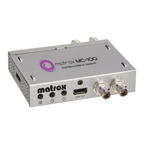
Connecting input and output devices The Matrox MC-100 unit supports two SDI input sources via two BNC input connectors, two SDI output devices via two BNC output connectors, and one HDMI output device. For a list of the supported input and output formats, see Appendix A, “Matrox MC-100 Supported Output Formats,”... -
Page 17: Using Your Matrox Mc-100 Hardware
Using Your Matrox MC-100 Hardware This chapter explains how to use your Matrox MC-100 hardware. -
Page 18: Overview
Green The output is supported. Red The output is not supported. • Power The LED is green when power is supplied to MC-100 and the hardware is functioning properly. ¦ Note If the MC-100 unit exceeds normal operating temperature, all four SDI LEDs will flash red as a warning. -
Page 19: Mc-100 Channel Definitions
SDI 1, and channel 2 refers to the input signal on SDI 2. • If one 3G level B input video signal is connected to MC-100, channel 1 and channel 2 refer to the two channels in the 3G level B signal. If you connect... -
Page 20: Amplifying Input Signals
• 3G 70 meters (229 feet) Time base correction and synchronization When input sources are connected to SDI 1 and SDI 2, MC-100’s time base corrector ensures that the two video signals are synchronized at the output by using the video signal that is set as the reference source (see “Specifying your... -
Page 21: Enabling The Loss-Of-Signal Switcher
In the event of a signal loss on the SDI 1 input, the MC-100 will automatically switch to the input on SDI 2 to output a video signal on SDI 4. The SDI 3 and HDMI outputs will display a purple screen as long as the signal on SDI 1 remains invalid. -
Page 22: Using The Osd Buttons
On the MC-100, turn on DIP switch 4 (turn the switch down) to enable the loss-of-signal switcher. For more information, see “Using the MC-100 DIP switches” on page 10. The loss-of-switcher feature is enabled, and will trigger a switch to the backup channel if a signal loss is detected on the main channel. - Page 23 Press any OSD button on the Matrox MC-100 unit. The Matrox MC-100 OSD main menu will appear on the display device connected to MC-100’s SDI and/or HDMI output. Select EXIT to close the OSD. Accessing the OSD main menu...
-
Page 24: Specifying Your Input Settings
Select INPUT from the OSD main menu. Select SIGNAL TYPE , and then select the setting that corresponds to the format of the input source connected to MC-100’s SDI input. For a list of the supported input video formats, see “Supported input formats”... -
Page 25: Viewing Input Information
• CHANNEL 1 FORMAT and CHANNEL 2 FORMAT Indicates the video format that is detected for channels 1 and 2. MC-100 cannot detect a PsF or dual link video signal. ¦ Note For more information on the MC-100 channels, see “MC-100 channel... -
Page 26: Specifying Your Output Settings
Select OUTPUT from the OSD main menu. For the SDI and HDMI outputs, select SDI 4 , SDI 3 , or HDMI , and then select your desired output setting. For information on the MC-100 channels, “MC-100 channel definitions” on page 11. - Page 27 SDI 1 bypass Outputs the video signal connected to input SDI 1 as is, without any processing. The MC-100 settings do not apply for this option. SDI 2 bypass Outputs the video signal connected to input SDI 2 as is, without any processing.
-
Page 28: Specifying Your 3D Settings
MC-100 channels. ° To set the 3D settings: Access the Matrox MC-100 on-screen display (OSD) main menu. Select 3D SETTINGS from the OSD main menu. Select 3D MODE , and then select the 3D viewing mode for channels 1 and 2. - Page 29 Remarks The 3D MODE option is not supported for 3G level A input signals. is not supported on the SDI outputs. Frame Packing Select ANALYSIS MODE , and then select the layering method that you want to use to analyze the two video input channels. This option is useful for finding disparities between the two input channel images.
-
Page 30: Using The Mc-100 Selection Modes
Using the MC-100 selection modes Matrox MC-100 offers different selection modes that allow you to quickly cycle through different output options without having to change the MC-100 settings. When using the MC-100 selection modes, the on-screen display (OSD) is replaced by a heads-up display (HUD) at the bottom of the video output that allows you to view the current selection mode setting. - Page 31 Outputs the video signal connected to input SDI 1 as is, SDI 1 bypass without any processing. The MC-100 settings do not apply for this option. SDI 2 bypass Outputs the video signal connected to input SDI 2 as is, without any processing.
-
Page 32: Saving Option Settings
DIP switches” on page for more information. The SAVE SETTINGS menu also allows you to restore the settings for the MC-100 options back to factory defaults. ¦ Note MC-100 can have only one user-defined preset loaded at any given time. - Page 33 Matrox MC-100 Supported Output Formats This appendix provides information on the output formats that are supported on Matrox MC-100.
-
Page 34: Matrox Mc-100 Supported Output Formats
Supported output formats when using input SDI 1 only The following table lists the video formats that are supported on the SDI and HDMI outputs based on the MC-100 output settings (see “Specifying your output settings” on page 18) when using an input source on SDI 1 only. -
Page 35: Input Source
Input source HDMI/SDI output format 3D Frame SDI 1 SDI 2 SDI 1 bypass SDI 2 bypass Channel 1 Channel 2 Analysis Multiplex Over/Under Side-by-Side Packing 1920×1080p at 1920×1080p at 1920×1080p at 50 fps — 50 fps — 50 fps —... -
Page 36: Supported Output Formats When Using Input Sdi 2 Only
Supported output formats when using input SDI 2 only The following table lists the video formats that are supported on the SDI and HDMI outputs based on the MC-100 output settings (see “Specifying your output settings” on page 18) when using an input source on SDI 2 only. - Page 37 Input source HDMI/SDI output format 3D Frame SDI 1 SDI 2 SDI 1 bypass SDI 2 bypass Channel 1 Channel 2 Analysis Multiplex Over/Under Side-by-Side Packing 1920×1080p at 1920×1080p at 1920×1080p at — 50 fps — 50 fps — 50 fps —...
-
Page 38: Supported Output Formats When Using Inputs Sdi 1 And Sdi 2
Supported output formats when using inputs SDI 1 and SDI 2 The following table lists the video formats that are supported on the SDI and HDMI outputs based on the MC-100 output settings (see “Specifying your output settings” on page 18) when using an input source on both SDI 1 and SDI 2. - Page 39 Input source HDMI/SDI output format 3D Frame SDI 1 SDI 2 SDI 1 bypass SDI 2 bypass Channel 1 Channel 2 Analysis Multiplex Over/Under Side-by-Side Packing 1920×1080PsF 1920×1080PsF 1920×1080PsF 1920×1080PsF — — — — — — — at 24 fps at 24 fps at 24 fps at 24 fps...
- Page 40 Your notes Appendix A, Matrox MC-100 Supported Output Formats...
- Page 41 Matrox MC-100 Specifications This appendix provides specifications for the Matrox MC-100.
-
Page 42: Matrox Mc-100 Specifications
Standard Type A HDMI connector (19 pins) • Display formats 3D display formats on SDI: Over/Under and Side-by-Side 3D display formats on HDMI: Over/Under, Side-by-Side, and Frame Packing Analysis mode display: Anaglyph, 50/50, and Difference Appendix B, Matrox MC-100 Specifications... -
Page 43: Environmental Specifications
• Minimum/maximum storage temperature: –40 to 75º C • Maximum altitude for operation: 3,000 meters • Maximum altitude for transport: 12,000 meters • Operating humidity: 20 to 80% relative humidity (non-condensing) • Storage humidity: 5 to 95% relative humidity (non-condensing) Matrox MC-100 specifications... - Page 44 Your notes Appendix B, Matrox MC-100 Specifications...
-
Page 45: Matrox Customer Support
Matrox Customer Support This appendix explains how you can register your Matrox product and obtain customer support. -
Page 46: How To Get Matrox Customer Support
Matrox product, please contact your Matrox representative. He or she should be able to help you quickly correct any installation or system configuration problem. If your representative is unable to solve your problem, contact Matrox for further information and assistance. Registration You can register your Matrox product in the Matrox Support section of our website at www.matrox.com/video/support. -
Page 47: Index
OSD specifying Display formats specifications vertical offset 3G level B channel definition Environmental specifications multiplexing Firmware, updating AC power to Matrox MC-100 Adapter plug connection Analysis HDMI output selecting audio output channel selection 3D settings connection mode specifications... - Page 48 On-screen display dimensions See OSD DIP switches display HUD on SDI output Operating safety feature of Matrox MC-100 display OSD on SDI output environmental specifications accessing main menu features display on SDI output flashing SDI LEDs...
- Page 49 Reference source priority Video, multiplexing Registering your Matrox product Regulatory compliance Warranty Returning procedure Warranty, standard WWW site, Matrox Safety feature when operating Matrox MC-100 SDI input connections specifications 26, 28, supported video formats SDI output connections specifications 26, 28,...
- Page 50 Your notes Index...
- Page 51 FCC Compliance Statement Remark for the Matrox hardware products supported by this guide These devices have been tested and found to comply with the limits for a Class B digital device, pursuant to Part 15 of the FCC Rules. These limits are designed to provide reasonable protection against harmful interference in a residential installation.
- Page 52 www.matrox.com/video...