Advertisement
Quick Links
TR-3
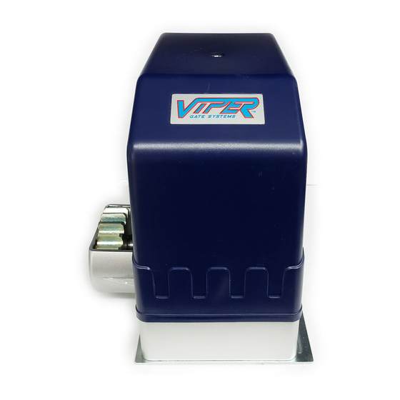
Residential Sliding Gate Opener
(Magnetic Limit Switch – Chain type)
Installation and Owner's Manual
For Residential use only – Class 1
(A Vehicular gate operator intended for use in a single family dwelling)
Made in the U.S.A.
This Product meets and exceeds the requirements of UL 325, the standard which regulates
gate operator safety, as established and made effective March 1, 2000, by Underwriters Laboratories Inc.
CAUTION: PLEASE READ THIS MANUAL CAREFULLY
GATEMOTORS INC.
PHONE: (352)241-8259
Email: Sales@Vipergatesystems.com
Advertisement

Summary of Contents for Viper TR-3
- Page 1 TR-3 Residential Sliding Gate Opener (Magnetic Limit Switch – Chain type) Installation and Owner’s Manual For Residential use only – Class 1 (A Vehicular gate operator intended for use in a single family dwelling) Made in the U.S.A. This Product meets and exceeds the requirements of UL 325, the standard which regulates gate operator safety, as established and made effective March 1, 2000, by Underwriters Laboratories Inc.
- Page 2 Important warning: CHILDREN should never be allowed to play near or operate automatic gates. Before attempting any part of the installation you must read the entire installation manual. The operator has to be grounded. When engaging and disengaging the emergency release with release key make sure the clutch is well tight to prevent any internal damage.
- Page 3 Thank you for purchasing the Sliding Gate Operator. Please read this user manual carefully before installation and use. Safety Read all Instructions completely before attempting installation and use failure to do so may result in serious injury or death. This operator is intended for use only vehicular gates. Pedestrians must be supplied with separate walkthrough gate.
- Page 5 TR-3 MODEL: COMPONENT COMPONENT MFR’S PART NO. QUANTITY DESCRIPTION MANUFACTURER Viper Gate Systems Cover tr3cov1 Viper Gate Systems Set Phillips screw tr3sps2 Viper Gate Systems ½ h.p. Motor tr3mot3 Viper Gate Systems Limit magnets tr3lm4 Viper Gate Systems Control board...
- Page 6 Concrete Pad and Base Installation Concrete Pad The concrete pad for operator mounting should be approximately 10” (255mm) x 12” (300mm) x 18” (460mm) deep in order to provide adequate weight and structure to insure proper stable installation. Be sure to position pad so it will not interfere with gate. Anchors You can use anchors that provided with the operator, 3¾...
- Page 7 MAIN BOARD / TERMINAL BLOCK 13 14 LIMIT LIMIT SWITCH CAPACITOR RECEIVER YELLOW / GREEN – Ground (ter. #22) MOTOR...
- Page 8 AC SLIDE GATE CONTROLLER FEATURE SELECTOR Limit Switch Type DIP 1 ON: Normally Close OFF: Normally Open When using auto close features only one dip switch should be it h h ld b Auto Close Feature Auto Close Feature DI P 2 12.5 Seconds ON. The other two dip switch DI P 3 25 Seconds should be in the OFF position for DI P 4 the auto close feature to work 45 Seconds correctly. Direction of Gate DI P 5 ON: Gate Opening to the left OFF: Gate Opening to the Right DI P 6 NOT USED Receiver DI P 7 Channel One (not used at this time) DI P 8 Channel Two (not used at this time)
- Page 9 Rack & Limit Switch Installation Power Connect 115Volt AC to terminals power to terminals 6 & 7 at high power side of the control board. (See Control board diagram at page 7) Rack Loosen the clutch by the release key (Insert key and turn Counter Clockwise to release the clutch). Attach the mounting bolts for the rack on the gate according to the specific position of the driving gear wheel and make sure that the rack is horizontal.
-
Page 10: Limit Switch Connections
Limit Switch Connections Terminal 1: Red wire will be connected here Terminal 2: White wire will be connected here Terminal 3: Green wire will be connected here NOTE: For left hand operation, reverse wires from terminals 1 and 3 Figure 7 Limit Switch Sensor The limit switch sensor is divided into two parts as seen in Figure 8. -
Page 11: Auto Close Timer
Manual Release Your Viper Gate System will include two keys that are used to disengage the operator from your gate in case of an emergency or power outage. Turn counter-clock-wise in the slot above to disengage the operator from the gate. This will allow you... - Page 12 Transmitter/Remote Control (shown in Figure 9) 1. Yellow Button Channel 2. Blue Button Channel 3. Indicator Light 4. Yellow Button Channel – exposed 5. DIP Switch 6. Battery 7. Blue Button Channel – exposed 8. Back side cover Figure 9 Receiver 1.
- Page 13 Viper Gate Systems Receiver Installation Figure 11 The receiver wiring to the control board will be set as follows: Terminal 1: Red wire Terminal 2: Black Wire Terminal 3: White Wire Terminal 4: White and Yellow Wire Terminal 5: Yellow Wire Your remotes are set from factory to use Channel 1 (the yellow button in Figure 9), to open and close the gate, and Channel 2 (the blue button in Figure 9) is to set to control an exterior light.
- Page 14 TR-3 Viper ™ Gate System Residential Sliding Gate Operator Optional Equipment Installation Procedures Green Brown Black Blue Brown Black White Grey Grey Black Black...

