Advertisement
Quick Links
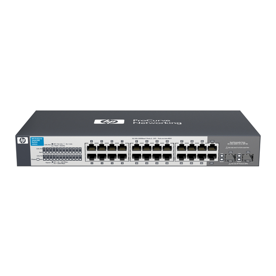
HP ProCurve 1410-24G Switch Quick Setup Guide
For more detailed information to set up your switch, view or download the Installation and Getting Started Guide for your
switch at www.hp.com/go/procurve/manuals.
1.
Unpack and check included parts.
2.
Prepare for installation. To avoid personal injury or product damage, review the "Safety Precautions" on
page 3.
3
. Connect power and verify that the switch power LED turns on. The switch does not contain a power switch. It is
turned on by connecting power through the AC power cord.
4.
Install the Switch Hardware. Turn off the switch before installing the switch hardware.
Table or Desktop: Attach the four self-adhesive pads
(included in the accessory kit) to the bottom corners of
the switch.
© Copyright 2010 Hewlett-Packard Development Company, L.P.
The information contained herein is subject to change without
notice.
Documentation kit
■
• Read Me First
• Quick Setup Guide
• Safety and Regulatory information
• Software License Agreement and Hardware Warranty
information
Switch
■
Accessory kit (installation hardware)
■
AC power cord
■
Power LED = On
1
Printed in China
February 2010
5998-0335
*5998-0335*
Advertisement

Related Manuals for HP ProCurve 1410-24G


Summary of Contents for HP ProCurve 1410-24G
- Page 1 HP ProCurve 1410-24G Switch Quick Setup Guide For more detailed information to set up your switch, view or download the Installation and Getting Started Guide for your switch at www.hp.com/go/procurve/manuals. Unpack and check included parts. Documentation kit ■ • Read Me First •...
- Page 2 (Optional) Lock the Switch. Use a Kensington lock or similar device (not included) to physically secure the switch. . Power On the Switch and Connect Network Cables. For transceiver connections, use only supported HP ProCurve mini-GBIC/SFP transceivers. After installing a transceiver, allow it to initialize (wait a few...
-
Page 3: Safety Precautions
Ensure the air flow around the switch is not restricted. Leave at least 7.6 cm (3 inches) for cooling. For other available ■ air flow information, see the Installation and Getting Started Guide for your product, located on the HP ProCurve Web site at www.hp.com/go/procurve/manuals. - Page 4 Wall Mounting Template for HP ProCurve 1410-24G Switch (Under-table mounting) After installation, prevent switch movement by placing a third screw along this side. 83.95 mm 3.31 Inch Screw-hole position for mounting 150.00 mm 5.91 inch...