Sony DCR-TRV240E Service Manual
Digital video camera recorder
Hide thumbs
Also See for DCR-TRV240E:
- Operating instructions manual (288 pages) ,
- Supplemental service manual (7 pages)
Table of Contents
Advertisement
DCR-TRV240E/TRV340E
SERVICE MANUAL
Level 1
Ver 1.1 2002. 06
Video camera
recorder
System
Video recording system
2 rotary heads
Helical scanning system
Audio recording system
Rotary heads, PCM system
Quantization: 12 bits (Fs 32 kHz,
stereo 1, stereo 2), 16 bits
(Fs 48 kHz, stereo)
Video signal
PAL colour, CCIR standards
Recommended cassette
Hi8/Digital8 video cassette
Recording/playback time (using
90 min. Hi8 video cassette)
SP mode: 1 hour
LP mode: 1 hour and 30 minutes
Fast-forward/rewind time (using
90 min. Hi8 video cassette)
Approx. 5 min.
Viewfinder
Electric Viewfinder, Monochrome
Image device
3 mm (1/6 type CCD)
(Charge Coupled Device)
Gross: Approx. 800 000 pixels
Effective: Approx. 400 000 pixels
Lens
Combined power zoom lens
Filter diameter 37 mm (1 1/2 in.)
25× (Optical), 700× (Digital)
Focal length
2.4 – 60 mm (1/8 – 2 3/8 in.)
When converted to a 35 mm still
camera
46 – 1 150 mm (1 13/16 – 45 3/8 in.)
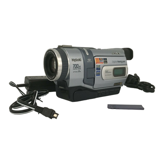
Photo : DCR-TRV240E
SPECIFICATIONS
Colour temperature
Auto
Minimum illumination
6 lx (lux) (F 1.6)
0 lx (lux) (in the NightShot mode)*
* Objects unable to be seen due to
the dark can be shot with infrared
lighting.
Input/output
connectors
S video input/output
4-pin mini DIN
Luminance signal: 1 Vp-p,
75 Ω (ohms), unbalanced
Chrominance signal: 0.3 Vp-p,
75 Ω (ohms), unbalanced
Audio/Video input/output
AV MINIJACK, 1 Vp-p, 75 Ω
(ohms), unbalanced, sync negative
327 mV, (at output impedance more
than 47 kΩ (kilohms))
Output impedance with less than
2.2 kΩ (kilohms)/Stereo minijack
(ø 3.5 mm)
Input impedance more than 47 kΩ
(kilohms)
Headphone jack
Stereo minijack (ø 3.5 mm)
USB jack
mini-B
LANC jack
Stereo mini-minijack (ø 2.5 mm)
MIC jack
Stereo minijack (ø 3.5 mm)
DV input/output
4-pin connector
DIGITAL VIDEO CAMERA RECORDER
East European Model
North European Model
2. GENERAL will be issued shortly.
LCD screen
Picture
6.2 cm (2.5 type)
50.3 × 37.4 mm (2 × 1 1/2 in.)
Total dot number
For European models:
123 200 (560 × 220)
For other countries' models:
61 600 (280 × 220)
General
Power requirements
7.2 V (battery pack)
8.4 V (AC power adaptor)
Average power consumption
(when using the battery pack)
During camera recording using
LCD
3.8 W
Viewfinder
3.0 W
Operating temperature
0°C to 40°C (32°F to 104°F)
Recommended charging
temperature
10°C to 30°C (50°F to 86°F)
Storage temperature
–20°C to + 60°C (–4°F to + 140°F)
Dimensions (approx.)
206 × 101 × 85 mm
(8 1/8 × 4 × 3 3/8 in.)
(w/h/d)
RMT-814
AEP Model
UK Model
Russian Model
M2000 MECHANISM
Mass (approx.)
DCR-TRV240E:
890 g (1 lb 15 oz)
DCR-TRV340E:
900 g (1 lb 15 oz)
excluding the battery pack, cassette,
lens cap and shoulder strap
DCR-TRV240E:
1 030 g (2 lb 4 oz)
DCR-TRV340E:
1 040 g (2 lb 4 oz)
including the battery pack
NP-FM30, 90min. Hi8 cassette, lens
cap and shoulder strap
Supplied accessories
See page 3.
AC power adaptor
Power requirements
100 – 240 V AC, 50/60 Hz
Power consumption
23 W
Output voltage
DC OUT: 8.4 V, 1.5 A in the
operating mode
Operating temperature
0°C to 40°C (32°F to 104°F)
Storage temperature
–20°C to + 60°C (–4°F to + 140°F)
Dimensions (approx.)
125 × 39 × 62 mm
(5 × 1 9/16 × 2 1/2 in. ) (w/h/d)
excluding projecting parts
Mass (approx.)
280 g (9.8 oz)
excluding mains lead
— Continued on next page —
Advertisement
Table of Contents

Related Manuals for Sony DCR-TRV240E


Summary of Contents for Sony DCR-TRV240E
- Page 1 SERVICE MANUAL AEP Model UK Model Level 1 East European Model Ver 1.1 2002. 06 North European Model Russian Model Photo : DCR-TRV240E M2000 MECHANISM 2. GENERAL will be issued shortly. SPECIFICATIONS Colour temperature Mass (approx.) LCD screen Video camera...
- Page 2 Danger of explosion if battery is incorrectly replaced. LIST ARE CRITICAL TO SAFE OPERATION. REPLACE THESE Replace only with the same or equivalent type. COMPONENTS WITH SONY PARTS WHOSE PART NUMBERS APPEAR AS SHOWN IN THIS MANUAL OR IN SUPPLEMENTS PUBLISHED BY SONY.
- Page 3 DCR-TRV240E/TRV340E Checking supplied accessories. Make sure that the following accessories are supplied with your camcorder. Wireless Remote Commander (1) AC power adaptor (1) Power cord (Main lead)(1) NP-FM30 battery pack (1) RMT-814 (AC-L10A) (AEP, EE, NE, RU model) (Not supplied)
-
Page 4: Table Of Contents
DCR-TRV240E/TRV340E TABLE OF CONTENTS SERVICE NOTE POWER SUPPLY DURING REPAIRS ····························· 5 TO TAKE OUT A CASSETTE WHEN NOT EJECT (FORCE EJECT) ································································ 5 SELF-DIAGNOSIS FUNCTION Self-diagnosis Function ······················································ 6 Self-diagnosis Display ························································ 6 Service Mode Display ························································ 6 3-1. Display Method ·································································· 6 3-2. -
Page 5: Service Note
DCR-TRV240E/TRV340E SERVICE NOTE POWER SUPPLY DURING REPAIRS In this unit, about 10 seconds after power is supplied (8.4V) to the battery terminal using the service power code (J-6082-223-A), the power is shut off so that the unit cannot operate. These following two methods are available to prevent this. Take note of which to use during repairs. -
Page 6: Self-Diagnosis Function
DCR-TRV240E/TRV340E SELF-DIAGNOSIS FUNCTION Self-diagnosis Function Self-diagnosis Display When problems occur while the unit is operating, the self-diagnosis When problems occur while the unit is operating, the counter of the function starts working, and displays on the viewfinder or Display viewfinder or Display window shows a 4-digit display consisting window what to do. -
Page 7: Self-Diagnosis Code Table
DCR-TRV240E/TRV340E Self-diagnosis Code Table Self-diagnosis Code Block Detailed Symptom/State Correction Function Code Non-standard battery is used. Use the InfoLITHIUM battery. Condensation. Remove the cassette, and insert it again after one hour. Video head is dirty. Clean with the optional cleaning cassette. - Page 8 DCR-TRV240E/TRV340E Self-diagnosis Code Block Detailed Symptom/State Correction Function Code Inspect the lens block focus reset sensor (Pin qd of CN1551 of Difficult to adjust focus VC-276 board) when focusing is performed when the focus ring is (Cannot initialize focus.) rotated in the focus manual mode and the focus motor drive circuit (IC1553 of VC-276 board) when the focusing is not performed.
-
Page 9: Main Parts
DCR-TRV240E/TRV340E 1. MAIN PARTS Note: • Follow the disassembly procedure in the numerical order given. The components identified by mark 0 or • Items marked “*” are not stocked since they are seldom required for routine service. dotted line with mark 0 are critical for safety. -
Page 10: Disassembly
DCR-TRV240E/TRV340E DISASSEMBLY The following flowchart shows the disassembly procedure. 2-1. LCD unit, PD-156 board 2-2. Front panel section, SI-032 board 2-3. Cabinet (R) section 2-12. Control switch block (CF-2500) 2-13. Control switch block (FK-2500) 2-14. Hinge section 2-4. Lens section 2-5. -
Page 11: Lcd Unit, Pd-156 Board
DCR-TRV240E/TRV340E Ver 1.1 2002. 06 NOTE: Follow the disassembly procedure in the numerical order given. 2-1. LCD UNIT, PD-156 BOARD REMOVING THE LCD P cabinet (C (2)) BLOCK ASSEMBLY P screw (M1.7 × 2.5) Remove the indication LCD block assembly in the direction of the arrow B . -
Page 12: Front Panel Section, Si-032 Board
DCR-TRV240E/TRV340E 2-2. FRONT PANEL SECTION, SI-032 BOARD The drum of mechanism deck. screws (M2 × 4) (H) Push the eject knob in the direction of the arrow A , and open the cassette lid. When removing Front panel section, do not press down the drum of mechanism deck. -
Page 13: Cabinet (R) Section
DCR-TRV240E/TRV340E 2-3. CABINET (R) SECTION screws Three claws 1 MI screw (M2 × 4) (H) (M2 × 4) (H) Three screws (M2 × 4) (H) 3 Cabinet (upper) Three screws (M2 × 4) (H) Claw 9 MI screw (M2 × 4) (H) -
Page 14: Lens Section, Cd-357 Board
DCR-TRV240E/TRV340E 2-4. LENS SECTION, CD-357 BOARD 2 FP-161 flexible board (16P) Two screws (M1.7 × 2.5), p 4 Lens section 3 Iris flexible assembly (24P) 2-5. EVF SECTION, LB-076 BOARD Routing of the flexible board 2 MI screw (TRV240E) (M2 × 4) (H) -
Page 15: Battery Panel Section, Battery Terminal
DCR-TRV240E/TRV340E 2-6. BATTERY PANEL SECTION, BATTERY TERMINAL BOARD screws (M2 × 4) (H) REMOVING THE 5 MI screw BATTERY TERMINAL BOARD (M2 × 4) (H) Tapping screw (M1.7 × 5) Battery terminal board 2 MI screw (M2 × 4) (H) -
Page 16: Control Switch Block (Ss-1380)
DCR-TRV240E/TRV340E 2-8. CONTROL SWITCH BLOCK (SS-1380) Routing of the flexible board of the Operation Push the eject knob in Control switch block (SS-1380). the direction of the arrow A , and open the cassette lid. 4 Two dowels Remove the control switch block (SS-1380) in the direction of the arrow B . -
Page 17: Vc-276 Board
DCR-TRV240E/TRV340E 2-10. VC-276 BOARD 8 VC-276 board 7 VC sheet - 2 7 a r d Two screws (M1.7 × 2.5), p Screw (M1.7 × 2.5), p FP-264 flexible 1 MI screw board (20P) (M2 × 4) (H) FP-410 flexible board 2-11. -
Page 18: Control Switch Block (Cf-2500)
DCR-TRV240E/TRV340E 2-12. CONTROL SWITCH BLOCK (CF-2500) Control switch block (FK-2500) (5P) Control switch block (CF-2500) Harness (PD-117) 6 Five tapping screws (6P) (B2 × 5) 1 MI screw (M2 × 4) (H) 6 Three tapping screws (B2 × 5) Routing of the harness (PD-117) . -
Page 19: Hinge Section
DCR-TRV240E/TRV340E 2-14. HINGE SECTION REMOVING THE HINGE ASSEMBLY Harness (PD-117) Remove the Harness (PD-117) (6, 20P) in the direction of the arrow 2 FP-412 flexible board (6P) Then bend the harness so that it is laid along with the connector. -
Page 20: Repair Parts List
DCR-TRV240E/TRV340E REPAIR PARTS LIST 3-1. EXPLODED VIEWS NOTE: • -XX, -X mean standardized parts, so they may • The mechanical parts with no reference number The components identified by mark 0 or have some differences from the original one. in the exploded views are not supplied. -
Page 21: Cabinet (L) Section-1
DCR-TRV240E/TRV340E 3-1-2. CABINET (L) SECTION-1 EVF section (See page 23) (TRV340E) Cabinet (L) section-2 (See page 22) - 2 7 a r d Mechanism deck Lens section (See page 23) Ref. No. Part No. Description Remarks Ref. No. Part No. -
Page 22: Cabinet (L) Section-2
DCR-TRV240E/TRV340E 3-1-3. CABINET (L) SECTION-2 ns : not supplied BT901 Ref. No. Part No. Description Remarks Ref. No. Part No. Description Remarks X-3951-159-1 CABINET (L) ASSY 4-974-725-01 SCREW (M1.7X2.5), P 3-052-815-01 BELT (ES), GRIP 3-941-343-21 TAPE (A) 3-067-347-01 MI SCREW M2 (H) -
Page 23: Lens, Evf Section
DCR-TRV240E/TRV340E 3-1-4. LENS, EVF SECTION ns : not supplied IC551 LCD903 M904 M905 Ref. No. Part No. Description Remarks Ref. No. Part No. Description Remarks not supplied DEVICE, LENS LSV-700A 1-683-624-11 FP-407 FLEXIBLE BOARD not supplied IRIS FLEXIBLE, ASSY not supplied... -
Page 24: Cabinet (R) Section
DCR-TRV240E/TRV340E 3-1-5. CABINET (R) SECTION ns : not supplied LCD section (See page 25) : The printed wiring board of the Control switch block (CF-2500) on which BT001 (lithium battery) is mounted, is not shown. Ref. No. Part No. Description Remarks Ref. -
Page 25: Lcd Section
DCR-TRV240E/TRV340E Ver 1.1 2002. 06 3-1-6. LCD SECTION LCD901 a r d ND901 D902 LCD902 Ref. No. Part No. Description Remarks Ref. No. Part No. Description Remarks 3-072-272-01 WINDOW, LCD 1-683-628-21 FP-412 FLEXIBLE BOARD X-3952-193-1 COVER (2) ASSY, CPC (TRV340E) - Page 26 DCR-TRV240E/TRV340E 2002F1600-1 Sony EMCS Co. 9-929-931-41 ©2002.6 — 26 — Published by DI Customer Center...
-
Page 27: Revision History
Reverse 992993142.pdf Revision History S.M. Rev. Ver. Date History Contents issued 2002.02 Official Release — — 2002.06 Correction-1 Correction of Disassembly and Exploded Views S.M. correction: Page 11,...