Table of Contents
Advertisement
Advertisement
Table of Contents

Related Manuals for Lowrance LRA-1000


Summary of Contents for Lowrance LRA-1000
-
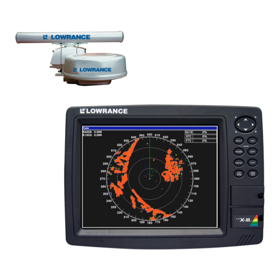
Page 1: Radar Operation
Pub. 988-0161-011 www.lowrance.com Radar Operation Instruction Manual... - Page 2 Copyright © 2006 Lowrance Electronics, Inc. All rights reserved. No part of this manual may be copied, reproduced, republished, trans- mitted or distributed for any purpose, without prior written consent of Lowrance Electronics. Any unauthorized commercial distribution of this manual is strictly prohibited. ...
-
Page 3: Table Of Contents
Warnings and Cautions ... iii Section 1: Introduction... 1 Models Covered ... 1 Update Display Unit Software ... 2 What is radar? ... 2 Basic Radar Display Components ... 4 Section 2: Radar Setup ... 7 Getting Started... 7 Radar Setup ... 9 Trigger Delay Preparation... - Page 4 Browse data files: ... 24 Copy data files: ... 25 Delete a data file:... 26 Stop or play a data file: ... 26 Rename a data file:... 26 Radar Setup ... 26 Radar Orientation ... 27 Radar Color Scheme... 27 Adjust Antenna Park ...
-
Page 5: Warnings And Cautions
Warnings and Cautions Caution: Use this radar at your own risk. This radar was designed for use as a navigation aid. It should not be used for purposes that require precise measurements of direction, distance, topography or location. Always compare the navigation information received from your radar with data from other navigation aids and sources. - Page 6 WARNING: Microwave Radiation Hazard The microwave energy radiated by a radar antenna is harmful to humans, especially to the eyes. NEVER look directly into an open waveguide or into the path of ra- diation from an enclosed antenna. Radar and other ra- dio frequency radiation can upset cardiac pacemakers.
-
Page 7: Section 1: Introduction
Section 1: Introduction Thank you for buying a Lowrance Radar with the RIM 100 radar inter- face module. Your radar consists of three main components: the radar scanner unit (antenna), your display unit (sold separately) and the RIM 100 radar interface module which connects the scanner and display units. WARNING: Radar radiation can be harmful to you and bystanders. -
Page 8: Update Display Unit Software
This manual covers the following radar units: LRA-1000, LRA-1500, LRA-2000 radomes; and LRA-4000, LRA-5000 open array radars. Update Display Unit Software Your display unit must have software version 1.3.0 or later to work with radar. Depending on when you bought your display, it may require a software update. - Page 9 When the echo returns, it is processed by a computer to determine rela- tive distance, position and bearing of the object that reflected the sig- nal. This information is displayed on the display unit's screen. Other boats or ships, navigational markers, landmasses and the like are re- ferred to as targets.
-
Page 10: Basic Radar Display Components
Basic Radar Display Components Range Display mode PPI Position status Electronic Bearing Lines Your unit has three electronic bearing lines and three variable range markers. Electronic Bearing Line position for EBLs 1, 2 and 3. Highlighted in white, EBL 2 is the active bearing line. - Page 11 Basic Radar Display Components PPI (radar screen's 360º overhead view of the area) Bearings, in degrees (in Heading Up mode, relative to bow) VRMs and EBLs allow you to track the distance and bearing NOTE: This manual is printed in black and white, but a free color version ...
- Page 12 Notes...
-
Page 13: Section 2: Radar Setup
Section 2: Radar Setup This section will teach you how to prepare your radar for operation. Be- fore you begin radar setup, the radar scanning unit, RIM 100 module and display unit must all be installed and their cables connected. The display unit must be running software version 1.3.0 or later. - Page 14 Radar only highlighted on Radar Pages menu (left). Radar menu with 6. Press , then use ↑ ↓ to select MENU and press . A confirmation message will appear. Press ← to select and press . A warm-up countdown will commence that will vary depending on the model of radar you have.
-
Page 15: Radar Setup
Radar Setup The Radar Setup menu allows you to setup and adjust radar settings, like Transmit Off Zone and Antenna Park. Most of the settings in the Radar Setup menu will only have to be set once, but we recommend you check the settings periodically for general maintenance. -
Page 16: Anti-Rain Clutter
Anti-Rain Clutter 1. To set Anti-Rain Clutter to zero, press and press (FTC) 2. That will launch the Anti-Rain Clutter vertical scrollbar. Press ↓ un- til the Anti-Rain Clutter is set to zero percent. Press corresponding value in the upper right-hand corner of the screen.) Main Bang Suppression 1. - Page 17 The 2 kW models, the LRA-1000 and LRA-1500, will have only one ring on the display. The 4 kW radars — LRA-2000, LRA-4000 and LRA-5000 — will have two rings on the display. See the following figures. Before adjusting the Trigger Delay for 4 kW radars, two rings will be shown on the screen (left).
-
Page 18: Adjust Main Bang Suppression
If you over apply the Trigger Delay, the black circle will disappear. De- crease the Trigger Delay level and it will reappear. 3. Press to return to the main page display. EXIT Adjust Main Bang Suppression Main Bang Suppression is only for 4kW units — This feature filters out electronic noise close to your vessel. -
Page 19: Adjust Heading Line
Main Bang Suppression begins with the same red ring we resized dur- ing Trigger Delay setup (left). Slowly increase Main Bang Suppression to make the ring as thin as possible (enlarged view, right). 5. Press to clear the scrollbar from the screen. Now reset Gain, EXIT Anti-Sea Clutter and Anti-Rain Clutter back to a desired level. -
Page 20: Adjust Transmit Off Zone
3. Use ← → to adjust the position of the green heading line, so its line to the reference point's radar image matches your bow's actual line to the reference point. 4. Press to remove the heading line arrows from the display. EXIT Adjust Transmit Off Zone The Transmit Off Zone is a feature that allows you to select an area in... -
Page 21: Adjust Tune
1. From the Radar Setup menu, press →|↓ to select DJUST RANSMIT and press . That will launch the Adjust Transmit Off Zone dialogs in the upper right-hand corner of the screen. 2, Use ↑ ↓, ← → to set up the Transmit Off Zone in the desired area. The zone will be colored red on the radar display. - Page 22 Notes...
-
Page 23: Section 3: Basic Operation
Section 3: Basic Operation Pages The Radar Page has four display options: Radar Only, Radar with Map, Radar with Sonar and Radar with Gauges. GPS only units do not sup- port the Radar with Sonar page, so they have three display options: Radar Only, Radar with Map and Radar with Gauges. -
Page 24: Radar With Sonar
Radar Only option (left) with Radar with Map display (right). Radar with Sonar The Radar with Sonar option allows you to monitor radar information, while viewing sonar returns. Not available on GPS only units. Radar with Gauges The Radar with Gauges display will split the screen between the radar page and the gauge page. -
Page 25: Radar Menu
Radar Menu When a radar page is the active page, you can access the radar menu by pressing . To access the main menu, press MENU Gain This is used to adjust the sensitivity of the receiver. Setting Gain to a low level will clear up some of the clutter on the screen, but also could eliminate some desired echoes. -
Page 26: Anti-Sea Clutter (Stc)
Gain vertical scrollbar (left) with Anti-Sea Clutter scrollbar (right). Anti-Sea Clutter (STC): This lowers receiver sensitivity at shorter ranges to reduce or eliminate echoes that reflect back at the antenna due to wave action close to the vessel. Caution Increasing STC may reduce or eliminate weak echoes, like small vessels. -
Page 27: Interference Rejection
Anti-Rain Clutter vertical scrollbar (left) with Interference Rejection Interference Rejection This feature filters out signals from other radars close to your location. To adjust Interference Rejection: 1. Select NTERFERENCE That will launch the Interference Rejection vertical scrollbar. 2. Use ↑ ↓ to adjust the Interference Rejection setting to a desired level. Press to remove the scrollbar from the screen. -
Page 28: Echo Trail Interval
Radar Range selected (left). List of radar ranges (right). To turn on or turn off Radar Echo Expansion: Highlight ADAR turn it on (check) or turn it off (uncheck). Press menu. Radar Echo Expansion is good for seeing weak echo returns — like birds —... -
Page 29: Adjust Radar Ppi Offset
Adjust Radar PPI Offset Adjusts vertical and horizontal offset of the PPI, allowing you to see more of what is in front, behind or on either side of you. To Adjust Radar PPI Offset: 1. Select DJUST ADAR 2. Four arrows will surround the PPI. Use ↑ ↓ , ← → to move the Plan Position Indicator (PPI) to the desired location. -
Page 30: Log Radar Data
Log Radar Data If your unit has a hard drive (LCX-26cHD, LCX-111cHD, GlobalMap 6600cHD & GlobalMap 7600cHD) the Log Radar Data feature allows you to save radar logs. Saving a radar log allows you to reuse the log in the unit's simulator, which can aid you in being more proficient at ra- dar interpretation. -
Page 31: Copy Data Files
Browse Files selected from the Radar Chart Logging menu (left). When you select a file from the file browse menu, you can copy, delete, play or stop playing a data file. To copy data files: 1. Select the desired file from the Browse Files menu and press 2. -
Page 32: Delete A Data File
4. Next use ↑ ↓ to highlight the hard drive as the Copy-From location and press 5. Highlight the To delete a data file: 1. Highlight ELETE 2. A confirmation message will appear. Press ← to To stop or play a data file: 1. -
Page 33: Radar Orientation
Transmit Off Zone and Tune, all of which are addressed in the section on Radar Setup. You can also modify Radar Orientation, Radar Color Scheme and Antenna Park from the Radar Setup menu. Radar Orientation Displays the orientation of your radar, which by default is set to Heading Up. -
Page 34: Radar Information
Selecting Adjust Antenna Park will place a dialog box in the upper right-hand corner of the screen. Use Arrow keys to adjust it. To adjust Antenna Park: 1. Make sure the vessel is not moving, then, from the Radar Setup menu, press →|↓... -
Page 35: Radar Power
Radar Information screen (left). Radar Power confirmation message Radar Power Turns the radar on and off. To turn radar on or off: 1. To turn the radar on or off, highlight and press 2. A confirmation message will appear. Press ← to Press to get back to the main page display. - Page 36 Simulators highlighted on the System Setup menu (left). Radar Simu- lator On selected on Radar Simulator menu (right). Notice the simula- tor has not been turned on, since the checkbox is unchecked. 5. Press ↓ to ADAR simulator checkbox. Repeat these steps to turn off the simulator. Press repeatedly to get back to the main page display.
-
Page 37: Section 4: Advanced Operation
Section 4: Advanced Operation Reading the Display The radar page displays digital information on the screen which covers, Range Rings, Gain, Anti-Sea Clutter (STC), Anti-Rain Clutter (FTC) and when active, Electronic Bearing Lines (EBL) and Variable Range Markers (VRM). Gain The percentage listed next to Gain, displays the current Gain setting for your radar display. -
Page 38: Anti-Sea Clutter (Stc)
Anti-Sea Clutter (STC) The STC percentage displays the current Anti-Sea Clutter setting on your radar screen. Anti-Rain Clutter (FTC) The FTC percentage displays the current Anti-Rain Clutter setting on your radar screen. Electronic Bearing Line (EBL) A radial line that can be rotated 360°, the electronic bearing line is used to monitor the bearing of a radar target in relation to your loca- tion. - Page 39 To find the distance to a radar target, increase the size of the VRM un- til it is lined up with the target. Check the display in the bottom right- hand corner to see your distance from the target in nautical miles. 4.
-
Page 40: Reposition Ebl And Vrm
3. Press ↓ to call up the EBL-VRM menu. Select the last EBL-VRM op- tion and press . Press ↑|→ to make the VRM and EBL visible on the screen, then press Variable Range Marker Radar Target This is a zoomed in view from the previous image, clearly showing the radar target, Variable Range Marker and Electronic Bearing Line. -
Page 41: Remove Ebl-Vrm From The Display
Radar screen with all three EBL-VRM options visible on the display. Notice the EBL and VRM readings in the bottom left and right-hand corners of the screen. To remove EBL-VRM from the display: 1. Press ↓ to call up the EBL-VRM menu. Select the EBL-VRM you want to remove and press 2. - Page 42 VRM2 EBL2 EBL3 VRM3 VRM1 EBL1 VRMs and EBLs allow you to track the distance and bearing of multiple radar targets.
-
Page 43: Section 5: Radar Interpretation
Section 5: Radar Interpretation Interpreting images on your radar screen involves as much art as it does science. If you want to be confident with your radar at night, you need to practice in daylight. To be ready for fog or a blinding rain squall, you must practice in fair weather. - Page 44 Anti-Rain Clutter (FTC) fig. 2. FTC set to 12% Anti-Rain Clutter (FTC) fig. 3. FTC set to 25 %.
- Page 45 Anti-Rain Clutter (FTC) fig. 4. FTC set to 50%. Anti-Rain Clutter (FTC) fig. 5. FTC set to 62%. The rain has virtually disappeared from the screen.
-
Page 46: Echo Trails
Echo Trails This four-figure sequence shows how Echo Trails tracks target move- ment over time. The boat is stationary. Several boats will be trailed. Color mode is default. Echo Trail update interval set to 30 seconds. Land mass is red; trail green will replace red as time... - Page 47 In fig. 3, note the target off the bow approaching at high speed from the north. The "dotted" trail indicates higher speed than targets with more solid trails. Be alert; this boat is a collision risk. Echo Trails fig. 3. Elapsed time = 8 seconds. Echo Trails fig.
-
Page 48: Typical Small Boat Targets
Typical Small Boat Targets Small boat targets fig. 1. Bow is headed into the wind. Here, boats ap- pear as larger red targets. Birds are smaller green targets. Small boat targets fig. 2. Boat has turned, with the wind (and wave Boats Birds Boat... - Page 49 Small boat targets fig. 3. Landmasses return a strong echo and thus appear red in default color mode. Small boat targets fig. 4. Three targets, with one boat just offshore. Boats Wave action Boat Bird Boat Wave action Boats...
-
Page 50: Shoreline Images
Shoreline Images This sequence illustrates a boat entering a channel. The green line is the track the vessel will take. The magenta line from the stern is a GPS trail. Study these radar returns with their corresponding maps and you'll get a feel for how radar displays a shoreline. This channel is sur- rounded by steeply sloping, rocky hills. - Page 51 Shoreline fig. 3. Shoreline fig. 4.
-
Page 52: Recommended Reading
Recommended Reading For additional instruction check out these two books and a U.S. gov- ernment manual: The Radar Book: Effective Navigation and Collision Avoidance, by Kevin Monahan. ISBN 1-932310-05-3, 235 pages, paperback. Published in 2003 by FineEdge.com LLC, 14004 Biz Point Lane, Anacortes, WA 98221 USA. -
Page 53: Appendix I: Glossary
Appendix I: Glossary Anti-Rain Clutter (FTC): used to reduce or eliminate massive num- ber of small echoes that clutter the display during rain or snow storms. Anti-Sea Clutter (STC): lowers receiver sensitivity at shorter ranges to reduce or eliminate sea clutter echoes, which are most prevalent around the vessel. - Page 54 Heading Line Adjustment: the Heading Line is used to make sure the green heading line (zero point) on your radar display is lined up the bow of your vessel. Heading Up: when your heading is displayed at the top of the screen, you are in Heading Up mode.
- Page 55 Transmit Off Zone: an area set up in the radar transmission path where the radar will not transmit a microwave pulse. Tuning: intermediate frequency adjustment that enhances the per- formance of the radar. VRM (Variable Range Marker): a range ring used to measure the precise distance to a target, the variable range marker may be adjusted to measure any distance within the radar's range.
-
Page 56: Fcc Compliance
This device complies with Part 15 and Part 80 of the U.S. Fed- eral Communications Commission (FCC) Rules. Operation is subject to the following two conditions: (1) this device may not cause harmful interference, and (2) this device must accept any interference received, including interference that may cause un- desired operation. - Page 57 LOWRANCE ELECTRONICS FULL ONE-YEAR WARRANTY "We," "our," or "us" refers to LOWRANCE ELECTRONICS, INC., the manufacturer of this product. "You" or "your" refers to the first person who purchases this product as a consumer item for personal, family or household use. We warrant this product against defects or malfunctions in materials and workmanship, and against failure to conform to this product's written specifications, all for one (1) year from the date of original purchase by you.
- Page 58 How to Obtain Service… …in the USA: We back your investment in quality products with quick, expert service and genuine Lowrance parts. If you're in the United States and you have technical, return or repair questions, please contact the Factory Customer Service Department.
- Page 59 Accessory Ordering Information for all countries To order Lowrance accessories for your unit, please contact: 1) Your local marine dealer or consumer electronics store. Most quality dealers that handle marine electronic equipment or other consumer electronics should be able to assist you with these items. To locate a Lowrance dealer near you, visit our web site, www.lowrance.com and look for the Dealer Locator.
- Page 60 Visit our web site: Lowrance Pub. 988-0161-011 © Copyright 2006 All Rights Reserved Printed in USA 033106 Lowrance Electronics, Inc.