Table of Contents
Advertisement
Quick Links
Advertisement
Table of Contents

Related Manuals for Supermicro X10DRT-H


Summary of Contents for Supermicro X10DRT-H
- Page 1 X10DRT-H X10DRT-HIBF USER’S MANUAL Revision 1.0a...
- Page 2 This product, including software and docu- mentation, is the property of Supermicro and/or its licensors, and is supplied only under a license. Any use or reproduction of this product is not allowed, except as expressly permitted by the terms of said license.
-
Page 3: About This Motherboard
Processors (Socket R3) that offer QPI (Intel QuickPath Interface) Technology, providing point-to-point connection with a transfer speed of up to 9.6 GT/s. With the PCH C612 built in, the X10DRT-H/HIBF motherboard supports Intel® Manage- ability Engine, Intel Rapid Storage Technology enterprise, Digital Media Interface (DMI), PCI-E Gen. -
Page 4: Conventions Used In The Manual
X10DRT-H/HIBF Motherboard User’s Manual Conventions Used in the Manual Pay special attention to the following symbols for proper system installation and to prevent damage to the system or injury to yourself: Warning: Important information given to ensure proper system installation or to prevent... -
Page 5: Contacting Supermicro
Super Micro Computer, Inc. 980 Rock Ave. San Jose, CA 95131 U.S.A. Tel: +1 (408) 503-8000 Fax: +1 (408) 503-8008 Email: marketing@supermicro.com (General Information) support@supermicro.com (Technical Support) Web Site: www.supermicro.com Europe Address: Super Micro Computer B.V. Het Sterrenbeeld 28, 5215 ML... -
Page 6: Table Of Contents
X10DRT-H/HIBF Motherboard User’s Manual Table of Contents Preface Chapter 1 Overview Overview ......................1-1 Processor and Chipset Overview ..............1-11 Special Features ................... 1-12 Recovery from AC Power Loss ..............1-12 System Health Monitoring ................1-12 Fan Status Monitor with Firmware Control ..........1-12 Environmental Temperature Control ............. - Page 7 Table of Contents Universal Serial Bus (USB) ..............2-16 Ethernet Ports ..................2-17 QSFP Connector (FDR 56 GT/s, for X10DRT-H/HIBF) ......2-18 COM1 ....................... 2-18 Video Connector ..................2-18 Unit Identifier Switch ................2-19 Front Panel Accessible Add-on Card Connector (JF1) ......... 2-20 Connecting Cables ..................
- Page 8 X10DRT-H/HIBF Motherboard User’s Manual Chapter 3 Troubleshooting Troubleshooting Procedures ................3-1 Before Power On .................... 3-1 No Power ......................3-1 No Video ......................3-2 System Boot Failure ..................3-2 Losing the System’s Setup Configuration ............3-2 Memory Errors ....................3-3 When the System Becomes Unstable ............
-
Page 9: Chapter 1 Overview
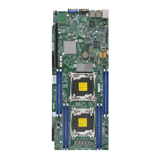
Checklist Congratulations on purchasing your computer motherboard from an acknowledged leader in the industry. Supermicro boards are designed with the utmost attention to detail to provide you with the highest standards in quality and performance. This motherboard was designed to be used with an Supermicro-proprietary chas- sis as an integrated server platform. - Page 10 X10DRT-H/HIBF Motherboard User’s Manual Motherboard Image Model Variations for X10DRT-H/-HIBF X10DRT-H X10DRT-HIBF LAN Ports Gigabit LAN1/2 Gigabit LAN1/2 IPMI/IPMI_LAN FDR IB Note: All graphics shown in this manual were based upon the latest PCB Revision available at the time of publishing of the manual. The motherboard you've received may or may not look exactly the same as the graphics shown in this manual.
- Page 11 Notes: 1. For the latest CPU/Memory updates, please refer to our website at http:// www.supermicro.com/products/motherboard/ for details. 2. Use only the correct type of onboard CMOS battery as specified by the manufacturer. Do not install the onboard battery upside down to avoid...
- Page 12 X10DRT-H/HIBF Motherboard User’s Manual X10DRT-H/HIBF Motherboard Quick Reference COM1 JCOM1 JVGA JUIDB1 JIB1 LAN2 LAN1 QSFP LEDBMC JUSBRJ45 JSTBY1 JPB1:BMC 1-2:ENABLE 2-3:DISABLE JBT1: CMOS CLEAR JSD2 CPU1 CLOSE 1st OPEN 1st CPU2 CLOSE 1st OPEN 1st Notes: • See Chapter 2 for detailed information jumpers, I/O ports, connectors and ex- pansion slots.
- Page 13 Chapter 1: Overview X10DRT-H/HIBF Motherboard Jumpers Jumper Description Default Setting JVRM1/JVRM2 C Bus for VRM Pins 1-2 (BMC: Normal) JBT1 Clear CMOS/Reset BIOS Configura- See Chapter 2 tion JPB1 BMC Enabled Pins 1-2 (Enabled) JPG1 VGA Enabled Pins 1-2 (Enabled)
- Page 14 X10DRT-H/HIBF Motherboard User’s Manual X10DRT-H/HIBF Motherboard LED Indicators State LED BMC (BMC Heartbeat LED) Green (Blinking): BMC Normal Hard Disk Drive Activity LED LED PWR Power LED LEB2 (X10DRT-HIBF) Green (On): InfiniBand On Blue: (On/Blinking) Unit Identifier...
-
Page 15: Motherboard Features
Graphics Controller 1920x1200@60Hz 32bpp • Network One Intel i350 Gigabit (10/100/1000 Mb/s) Ethernet Dual-Channel controller for GLAN 1/GLAN 2 ports (X10DRT-H/HIBF) I/O Devices Connect-X3 Port (X10DRT-HIBF) • Used as InfiniBand QDR 40 GT/s or FDR 56 GT/s (4-channel) Small Form-factor Pluggable (QSFP) -
Page 16: Peripheral Devices
X10DRT-H/HIBF Motherboard User’s Manual IPMI 2.0 • IPMI 2.0 supported by the ASpeed 2400 BMC Serial (COM) Port • One (1) Fast UART 16550 Connection: 9-pin RS- 232 port • Rear VGA Port Peripheral USB Devices Devices • Two (2) USB ports on the rear I/O panel (USB 3.0) Ports USB 0/1 •... - Page 17 Chapter 1: Overview • UID/Remote UID LED • CPU/System Overheat LED • Power/Suspend State LED • HDD Activity LED • LAN Activity LED • System PECI (Platform Environment Configuration Interface) Management 2.0 support • System resource alert via SuperDoctor® 5 •...
-
Page 18: System Block Diagram
X10DRT-H/HIBF Motherboard User’s Manual X10DRT-H VR12.5 VR12.5 #2-4 #1-4 5 PHASE 5 PHASE #2-3 145W 145W #1-3 #2-2 #1-2 #2-1 #1-1 Haswell Haswell 9.6G SNB CORE SNB CORE DDR-IV DDR-IV 9.6G Mellanox CX3 PCI-E X8 G3 IB QDR/FDR PCI-E X8 G3... -
Page 19: Processor And Chipset Overview
Processor and Chipset Overview Built upon the functionality and capability of the Intel E5-2600(V3) Series proces- sors (Socket R3) and the Intel C612 PCH, the X10DRT-H Series motherboard provides the best balanced solution of performance, power efficiency, and features to address the diverse needs of next-generation data centers. -
Page 20: Special Features
X10DRT-H/HIBF Motherboard User’s Manual Special Features Recovery from AC Power Loss The Basic I/O System (BIOS) provides a setting that determines how the system will respond when AC power is lost and then restored to the system. You can choose for the system to remain powered off (in which case you must press the power switch to turn it back on), or for it to automatically return to the power-on state. -
Page 21: Acpi Features
Serial Port The X10DRT-H/HIBF motherboard supports one serial communication connection. COM Port 1 can be used for input/output. The UART provide legacy speed with baud rate of up to 115.2 Kbps as well as an advanced speed with baud rates of 250 K, 500 K, or 1 Mb/s, which support high-speed serial communication devices. -
Page 22: Advanced Power Management
X10DRT-H/HIBF Motherboard User’s Manual Advanced Power Management The following new advanced power management features are supported by the motherboard. Intel Intelligent Power Node Manager (NM) (Available ® when the NMView software is installed) The Intel Intelligent Power Node Manager (IPNM) provides your system with ®... -
Page 23: Chapter 2 Installation
The following statements are industry-standard warnings, provided to warn the user of situations which have the potential for bodily injury. Should you have questions or experience difficulty, contact Supermicro's Technical Support department for assis- tance. Only certified technicians should attempt to install or configure components. - Page 24 X10DRT-H/HIBF Motherboard User’s Manual Attention Danger d'explosion si la pile n'est pas remplacée correctement. Ne la remplacer que par une pile de type semblable ou équivalent, recommandée par le fabricant. Jeter les piles usagées conformément aux instructions du fabricant. ¡Advertencia! Existe peligro de explosión si la batería se reemplaza de manera incorrecta.
-
Page 25: Product Disposal
Chapter 2: Installation Product Disposal Warning! Ultimate disposal of this product should be handled according to all national laws and regulations. 製品の廃棄 この製品を廃棄処分する場合、 国の関係する全ての法律 ・ 条例に従い処理する必要が あり ます。 警告 本产品的废弃处理应根据所有国家的法律和规章进行。 警告 本產品的廢棄處理應根據所有國家的法律和規章進行。 Warnung Die Entsorgung dieses Produkts sollte gemäß allen Bestimmungen und Gesetzen des Landes erfolgen. -
Page 26: Static-Sensitive Devices
X10DRT-H/HIBF Motherboard User’s Manual Static-Sensitive Devices Electrostatic Discharge (ESD) can damage electronic com ponents. To avoid pos- sible damage to your system board, it is important to handle it very carefully. The following measures are generally sufficient to protect your equipment from ESD. -
Page 27: Processor And Heatsink Installation
CPU socket cap is in place and none of the socket pins are bent; otherwise, contact your retailer immediately. • Refer to the Supermicro website for updates on CPU support. Installing the LGA2011 Processor 1. There are two load levers on the LGA2011 socket. To open the socket cover, first press and release the load lever labeled 'Open 1st'. - Page 28 X10DRT-H/HIBF Motherboard User’s Manual 2. Press the second load lever labeled 'Close 1st' to release the load plate that covers the CPU socket from its locking position. Pull lever away from Press down on Load the socket Lever 'Close 1st' 3.
- Page 29 Chapter 2: Installation 1. Using your thumb and the index finger, remove the 'WARNING' plastic cap from the socket. 2. Use your thumb and index finger to hold the CPU on its edges. Align the CPU keys, which are semi-circle cutouts, against the socket keys. Socket Keys CPU Keys 3.
- Page 30 X10DRT-H/HIBF Motherboard User’s Manual 4. With the CPU inside the socket, inspect the four corners of the CPU to make sure that the CPU is properly installed. 5. Close the load plate with the CPU inside the socket. Lock the 'Close 1st' le- ver first, then lock the 'Open 1st' lever second.
-
Page 31: Installing A Passive Cpu Heatsink
Chapter 2: Installation Installing a Passive CPU Heatsink 1. Apply the proper amount of thermal grease to the heatsink. 2. Place the heatsink on top of the CPU so that the two mounting holes on the heatsink are aligned with those on the retention mechanism. 3. -
Page 32: Removing The Passive Heatsink
X10DRT-H/HIBF Motherboard User’s Manual Removing the Passive Heatsink Warning: We do not recommend that the CPU or the heatsink be removed. However, if you do need to remove the heatsink, please follow the instructions below to uninstall the heatsink to avoid damaging the CPU or other components. -
Page 33: Installing And Removing The Memory Modules
Chapter 2: Installation Installing and Removing the Memory Modules Note: Check Supermicro's website for recommended memory modules. CAUTION Exercise extreme care when installing or removing DIMM modules to prevent any possible damage. Installing & Removing DIMMs 1. Insert the desired number of DIMMs into the memory slots, starting with P1-DIMMA1. - Page 34 X10DRT-H/HIBF Motherboard User’s Manual Memory Support for the X10DRT-H/HIBF Motherboard The X10DRT-H/HIBF motherboard upports up to 512GB of DDR4 Registered (RDIMM)/Load Reduced (LRDIMM) EEC 1333/1600/1866*/2133** MHz memory modules in eight DIMM slots (*Maximum for 2 DIMMs per channel, ** Maximum for 1 DIMM per channel).
- Page 35 Chapter 2: Installation Populating DDR4 DIMM Memory Modules Type Ranks DIMM Capac- Speed (MT/s); Voltage (V); Slot per Chan- ity (GB) nel (SPC) and DIMM Per Channel (DPC) DIMM 1 Slot 2 Slots Per 3 Slots Per Channel & Data Channel Width Chan-...
-
Page 36: Motherboard Installation
X10DRT-H/HIBF Motherboard User’s Manual Motherboard Installation All motherboards have standard mounting holes to fit different types of chassis. Make sure that the locations of all the mounting holes for both motherboard and chassis match. Although a chassis may have both plastic and metal mounting fas- teners, metal ones are highly recommended because they ground the motherboard to the chassis. -
Page 37: Control Panel Connectors And I/O Ports
Chapter 2: Installation Control Panel Connectors and I/O Ports The I/O ports are intended to be used in Supermicro Twin servers. See the picture below for the locations of I/O ports. Back Panel Connectors and I/O Ports COM1 JVGA JCOM1... -
Page 38: Universal Serial Bus (Usb)
X10DRT-H/HIBF Motherboard User’s Manual Universal Serial Bus (USB) USB (3.0) 0/1 Pin Definitions Two USB 3.0 connections are on the X10DRT. Pin# Definition Two USB 3.0 ports are located on the I/O back panel (USB 0/1). (Cables are not included.) See the tables on the right for pin definitions. -
Page 39: Ethernet Ports
Ethernet Ports Two Ethernet ports (LAN1/2) are located on the I/O backpanel on the motherboard. These two LAN ports support Gigabit LAN connections on the X10DRT-H/HIBF. In addition, an IPMI_Dedicated LAN is located above USB 0/1 (3.0) ports on the backpanel to provide KVM support for IPMI 2.0. -
Page 40: Qsfp Connector (Fdr 56 Gt/S, For X10Drt-H/Hibf)
X10DRT-H/HIBF Motherboard User’s Manual QSFP Connector (FDR 56 GT/s, for X10DRT-H/HIBF) The Quad Connector-X3 FDR 56 GT/s (4-channel) Small Form-factor Pluggable (QSFP) connector, used as an InfiniBand (IB) port, is located on the backpanel on the X10DRT-HIBF. The IB connection is primarily used for High-performance computing. -
Page 41: Unit Identifier Switch
Chapter 2: Installation Unit Identifier Switch A Unit Identifier (UID) Switch (SW1) and an LED Indicator are located on the moth- erboard. The rear UID is located next to the QSFP port, and the Rear UID LED is located at UID_LED1. When the user presses a UID switch, the UID LED Indicator will be turned on. -
Page 42: Front Panel Accessible Add-On Card Connector (Jf1)
Panel Control connections for the X10DRT series motherboard. Insert an Add-On card into this connector to use the functions indicated above. This connector is designed specifically for a Supermicro-proprietary add-on card. Refer to the layout below for the location of JF1. -
Page 43: Connecting Cables
Chapter 2: Installation Connecting Cables IPMB I C SMB SMB Header Pin Definitions A System Management Bus header Pin# Definition for the IPMI slot is located at JIPMB1. Data Connect an appropriate cable here to Ground use the IPMB I C connection on your Clock system. -
Page 44: Dom Power Connector
X10DRT-H/HIBF Motherboard User’s Manual DOM Power Connector DOM PWR Pin Definitions A power connector for SATA DOM (Disk_ Pin# Definition On_Module) devices is located at JSD1 and JSD2. Connect an appropriate cable here to Ground provide external power for 3rd party SATA... -
Page 45: Fan Header
Chapter 2: Installation Fan Header Fan Header Pin Definitions This motherboard has one system cooling Pin# Definition fan header (Fan 3) on the motherboard. Ground This 4-pin fan header is backward com- +12V patible with the traditional 3-pin fans. Tachometer However, fan speed control is available PWR Modulation for 4-pin fans only. -
Page 46: Tpm Header/Port 80
Definition er is located at JTPM1 to provide TPM LCLK support and Port 80 connection. Use this LFRAME <(KEY)> header in conjunction with a Supermicro LRESET VCC5 TPM 1.2/2.0 module to enhance system LAD3 LAD2 data security. Contact your Supermicro... -
Page 47: Jumper Settings
Chapter 2: Installation Jumper Settings Explanation of Jumpers Connector Pins To modify the operation of the motherboard, jumpers can be used to choose between optional settings. Jumpers create shorts Jumper between two pins to change the function of the connector. Pin 1 is identified with a square solder pad on the printed circuit Setting board. -
Page 48: Clear Cmos
X10DRT-H/HIBF Motherboard User’s Manual Clear CMOS JBT1 is used to clear CMOS. Instead of pins, this "jumper" consists of contact pads to prevent accidental clearing of CMOS. To clear CMOS, use a metal object such as a small screwdriver to touch both pads at the same time to short the connection. -
Page 49: Vga Enable
Chapter 2: Installation VGA Enable VGA Enable Jumper Settings Jumper JPG1 allows the user to enable Jumper Setting Definition the onboard VGA support. The default Enabled (Default) setting is 1-2, enabled. See the table on Disabled the right for jumper settings. BMC Enable BMC Enable Jumper Settings... -
Page 50: I 2 C Bus For Vrm
X10DRT-H/HIBF Motherboard User’s Manual C Bus for VRM I2C Bus for VRM Jumper Settings Jumpers JVRM1 and JVRM2 allow the BMC Jumper Setting Definition or the PCH to access CPU and memory VRM Enabled (Default) controllers. See the table on the right for jumper Disabled settings. -
Page 51: Ji2C1 And Ji2C2
Chapter 2: Installation JI2C1 and JI2C2 to PCI-Exp Jumper Settings Jumpers JI C1 and JI C2 allows the Jumper Setting Definition connection of the the System Manage- Enabled ment Bus (I C) to PCI-Express slots. The Normal (Default) default setting is on pins 2-3 for normal operation. -
Page 52: Onboard Led Indicators
X10DRT-H/HIBF Motherboard User’s Manual Onboard LED Indicators LAN LEDs Activity LED Link LED The LAN ports are located on the IO backpanel on the motherboard. Each Ether- GLAN Activity Indicator (Right) LED Settings net LAN port has two LEDs. The yellow LED... -
Page 53: Bmc Heartbeat Led
Chapter 2: Installation BMC Heartbeat LED BMC Heartbeat LED Status A BMC Heartbeat LED is located at BMC_ Color/State Definition HB_LED1 on the motherboard. When this Green: BMC: Normal LED is blinking, BMC functions normally. Blinking See the table at right for more information. Hard Disk Activity LED Hard Disk Activity LED Status... -
Page 54: Infiniband Link Indicator (For The X10Drt-Hibf Only)
X10DRT-H/HIBF Motherboard User’s Manual InfiniBand Link Indicator (For the InfiniBand Link LED X10DRT-HIBF Only) Settings Color Status Definition An InfiniBand Link LED Indicator is located Green Solid InfiniBand on the motherboard. Refer to the table on Connected the right for details. Also see the layout No connection below for the LED location. -
Page 55: Rear Uid Led
Chapter 2: Installation Rear UID LED UID LED Status The rear UID LED is located at UID_LED1 Color/State OS Status on the rear of the motherboard. This LED Blue: On Windows OS Unit Identified is used in conjunction with the rear UID Blue: Linux OS Unit Identified... -
Page 56: 2-10 Sata And Pci-E 3.0 Slots
X10DRT-H/HIBF Motherboard User’s Manual 2-10 SATA and PCI-E 3.0 Slots CPU1 PCI-Express 3.0 x8 (in x4) Slot (SXB1) CPU2 PCI-Express 3.0 x8 (in x4) Slot (SXB2) CPU1 Slot1 PCI-Express 3.0 x16 There are several PCI slots located on the motherboard. Refer to the layout below for the locations. -
Page 57: Chapter 3 Troubleshooting
Chapter 3: Troubleshooting Chapter 3 Troubleshooting Troubleshooting Procedures Use the following procedures to troubleshoot your system. If you have followed all of the procedures below and still need assistance, refer to the ‘Technical Support Procedures’ and/or ‘Returning Merchandise for Service’ section(s) in this chapter. Note: Always disconnect the power cord before adding, changing or install- ing any hardware components. -
Page 58: No Video
X10DRT-H/HIBF Motherboard User’s Manual No Video 1. If the power is on, but you do not have video, remove all the add-on cards and cables. 2. Use the speaker to determine if any beep codes exist. Refer to Appendix A for details on beep codes. -
Page 59: Memory Errors
2. Memory support: Make sure that the memory modules are supported by test- ing the modules using memtest86 or a similar utility. Note: Refer to the product page on our website http:\\www.supermicro. com for memory and CPU support and updates. - Page 60 X10DRT-H/HIBF Motherboard User’s Manual tings in the IPMI to make sure that the CPU and System temperatures are within the normal range. Also check the front panel Overheat LED, and make sure that the Overheat LED is not on. 5. Adequate power supply: Make sure that the power supply provides adequate power to the system.
-
Page 61: Technical Support Procedures
Technical Support Procedures Before contacting Technical Support, please take the following steps. Also, please note that as a motherboard manufacturer, Supermicro also sells motherboards through its channels, so it is best to first check with your distributor or reseller for troubleshooting services. -
Page 62: Proper Battery Disposal
X10DRT-H/HIBF Motherboard User’s Manual Battery Removal and Installation Battery Removal To remove the onboard battery, follow the steps below: 1. Power off your system and unplug your power cable. 2. Locate the onboard battery as shown below. 3. Using a tool such as a pen or a small screwdriver, push the battery lock out- wards to unlock it. -
Page 63: Frequently Asked Questions
Note: The SPI BIOS chip used on this motherboard cannot be removed. Send your motherboard back to our RMA Department at Supermicro for repair. For BIOS Recovery instructions, please refer to the AMI BIOS Recovery Instructions posted at http://www.supermicro.com. -
Page 64: Returning Merchandise For Service
X10DRT-H/HIBF Motherboard User’s Manual Returning Merchandise for Service A receipt or copy of your invoice marked with the date of purchase is required before any warranty service will be rendered. You can obtain service by calling your ven- dor for a Returned Merchandise Authorization (RMA) number. When returning the... -
Page 65: Chapter 4 Bios
BIOS Introduction This chapter describes the AMI BIOS Setup utility for the X10DRT-H/HIBF. It also provides the instructions on how to navigate the AMI BIOS Setup utility screens. The AMI ROM BIOS is stored in a Flash EEPROM and can be easily updated. -
Page 66: How To Change The Configuration Data
X10DRT-H/HIBF Motherboard User’s Manual How To Change the Configuration Data The configuration data that determines the system parameters may be changed by entering the AMI BIOS Setup utility. This Setup utility can be accessed by pressing <F2> at the appropriate time during system boot. - Page 67 This item displays the system date in Day MM/DD/YY format (e.g. Wed 10/12/2011). System Time This item displays the system time in HH:MM:SS format (e.g. 15:32:52). Supermicro X10DRT-H BIOS Version This item displays the version of the BIOS ROM used in this system.
-
Page 68: Advanced Setup Configurations
X10DRT-H/HIBF Motherboard User’s Manual Advanced Setup Configurations Use the arrow keys to select Advanced Setup and press <Enter> to access the following submenu items. Boot Features Quiet Boot This feature selects the bootup screen display between POST messages and the OEM logo. Select Disabled to display the POST messages. Select Enabled to display the OEM logo instead of the normal POST messages. -
Page 69: Power Configuration
Chapter 4: AMI BIOS Interrupt 19 Capture Interrupt 19 is the software interrupt that handles the boot disk function. When this item is set to Enabled, the ROM BIOS of the host adaptors will "capture" Interrupt 19 at bootup and allow the drives that are attached to these host adaptors to function as bootable disks. -
Page 70: Cpu Configuration
X10DRT-H/HIBF Motherboard User’s Manual CPU Configuration This submenu displays the information of the CPU as detected by the BIOS. It also allows the user to configuration CPU settings. Socket 1 CPU Information/Socket 2 CPU Information This submenu displays the following information regarding the CPU installed in Socket 1 and (or) Socket 2 as detected by the BIOS. - Page 71 Chapter 4: AMI BIOS Execute-Disable Bit Capability (Available if supported by the OS & the CPU) Select Enabled to enable the Execute-Disable Bit which will allow the processor to designate areas in the system memory where an application code can execute and where it cannot, thus preventing a worm or a virus from flooding illegal codes to overwhelm the processor or damage the system during an attack.
-
Page 72: Cpu Power Management Configuration
X10DRT-H/HIBF Motherboard User’s Manual Intel® Virtualization Technology (Available when supported by the CPU) Select Enabled to support Intel Virtualization Technology, which will allow one platform to run multiple operating systems and applications in independent parti- tions, creating multiple "virtual" systems in one physical computer. The options are Enabled and Disabled. -
Page 73: Chipset Configuration
Chapter 4: AMI BIOS CPU C State Control Package C-State limit This feature allows the user to set the limit on the C-State package register. The options are C0/C1 State, C2 State, C6 (Non Retention) State, and C6 (Rententioin) State. CPU C3 Report Select Enabled to allow the BIOS to report the CPU C3 State (ACPI C2) to the operating system. - Page 74 X10DRT-H/HIBF Motherboard User’s Manual IIO1 Configuration IOU2 (II0 PCIe Port 1) This item configures the PCI-E port Bifuraction setting for a PCI-E port specified by the user. The options are x4x4, X8, and Auto. IOU0 (II0 PCIe Port 2) This item configures the PCI-E port Bifuraction setting for a PCI-E port specified by the user.
- Page 75 Chapter 4: AMI BIOS IOU1 (II02 PCIE Port 3) Use this item to configure the PCI-E port Bifuraction setting for a PCI-E port speci- fied by the user. The options are x4x4x4x4, x4x4x8, x8x4x4, x8x8, x16, and Auto. IOAT (Intel® IO Acceleration) Configuration Enable IOAT Select Enable to enable Intel I/OAT (I/O Acceleration Technology) support, which significantly reduces CPU overhead by leveraging CPU architectural improve-...
- Page 76 X10DRT-H/HIBF Motherboard User’s Manual QPI (Quick Path Interconnect) Configuration QPI General Configuration QPI Status The following information will display: • Number of CPU • Number of IIO • Current QPI Link Speed • Current QPI Link Frequency • QPI Global MMIO Low Base/Limit •...
-
Page 77: Memory Configuration
Chapter 4: AMI BIOS Memory Configuration Enforce POR Select Enable to enforce POR restrictions on DDR4 frequency and voltage programming. The options are Enabled and Disabled. Memory Frequency Use this feature to set the maximum memory frequency for onboard memory modules. - Page 78 X10DRT-H/HIBF Motherboard User’s Manual Memory RAS (Reliability Availability Serviceability) Configuration Use this submenu to configure the following Memory RAS settings. RAS Mode When Disable is selected, RAS is not supported. When Mirror is selected, the motherboard maintains two identical copies of all data in memory for data backup.
-
Page 79: South Bridge Configuration
Chapter 4: AMI BIOS South Bridge Configuration The following South Bridge information will display: USB Configuration • USB Module Version • USB Devices Legacy USB Support Select Enabled to support onboard legacy USB devices. Select Auto to disable legacy support if there are no legacy USB devices present. -
Page 80: Sata Configuration
X10DRT-H/HIBF Motherboard User’s Manual EHCI2 Select Enabled to enable EHCI (Enhanced Host Controller Interface) support on USB 2.0 connector #2 (-at least one USB 2.0 connector should be enabled for EHCI support.) The options are Disabled and Enabled. XHCI Pre-Boot Drive Select Enabled to enable XHCI (Extensible Host Controller Interface) support on a pre-boot drive specified by the user. - Page 81 Chapter 4: AMI BIOS Port 0~ Port 5 Select Enabled to enable a SATA port specified by the user. The options are Disabled and Enabled. Port 0 ~ Port 5 Spin Up Device On an edge detect from 0 to 1, set this item to allow the PCH to initialize the device.
-
Page 82: Ssata Configuration
X10DRT-H/HIBF Motherboard User’s Manual Serial ATA Port 0~ Port 5 This item displays the information detected on the installed SATA drives on the particular SATA port. • Model number of drive and capacity • Software Preserve Support Port 0~ Port 5 Select Enabled to enable a SATA port specified by the user. - Page 83 Chapter 4: AMI BIOS Support Aggressive Link Power Management When this item is set to Enabled, the SATA AHCI controller manages the power usage of the SATA link. The controller will put the link to a low power state when the I/O is inactive for an extended period of time, and the power state will return to normal when the I/O becomes active.
- Page 84 X10DRT-H/HIBF Motherboard User’s Manual Support Aggressive Link Power Management When this item is set to Enabled, the SATA AHCI controller manages the power usage of the SATA link. The controller will put the link to a low power state when the I/O is inactive for an extended period of time, and the power state will return to normal when the I/O becomes active.
- Page 85 Chapter 4: AMI BIOS Server ME (Management Engine) Configuration This feature displays the following system ME configuration settings. • General ME Configuration • Operational Firmware Version • Recovery Firmware Version • ME Firmware Features • ME Firmware Status #1 • ME Firmware Status #2 •...
- Page 86 X10DRT-H/HIBF Motherboard User’s Manual Maximum Payload Select Auto for the system BIOS to automatically set the maximum payload value for a PCI-E device to enhance system performance. The options are Auto, 128 Bytes, and 256 Bytes. Maximum Read Request Select Auto for the system BIOS to automatically set the maximum size for a read request for a PCI-E device to enhance system performance.
-
Page 87: Super Io Configuration
Chapter 4: AMI BIOS Onboard LAN1 Option ROM Onboard LAN2 Option ROM Onboard Video Option ROM Use this option to select the type of device installed in LAN Port1, LAN Port2, LAN Port3, LAN Port4, or the onboard video device used for system boot. The default setting for LAN1 Option ROM is PXE, Disabled for LAN2 Option ROM, and Legacy for Onboard Video Option ROM. -
Page 88: Serial Port Console Redirection
X10DRT-H/HIBF Motherboard User’s Manual Serial Port 2 Attribute Select SOL to use COM Port 2 as a Serial_Over_LAN (SOL) port for console redi- rection. The options are COM and SOL. Serial Port Console Redirection COM 1 COM 1 Console Redirection Select Enabled to enable COM Port 1 Console Redirection, which will allow a client machine to be connected to a host machine at a remote site for networking. - Page 89 Chapter 4: AMI BIOS Stop Bits A stop bit indicates the end of a serial data packet. Select 1 Stop Bit for standard serial data communication. Select 2 Stop Bits if slower devices are used. The options are 1 and 2. Flow Control Use this item to set the flow control for Console Redirection to prevent data loss caused by buffer overflow.
- Page 90 X10DRT-H/HIBF Motherboard User’s Manual SOL/COM1 Console Redirection Select Enabled to use the SOL port for Console Redirection. The options are Enabled and Disabled. *If the item above set to Enabled, the following items will become available for user's configuration: SOL/COM2 Console Redirection Settings Use this feature to specify how the host computer will exchange data with the client computer, which is the remote computer used by the user.
- Page 91 Chapter 4: AMI BIOS Stop Bits A stop bit indicates the end of a serial data packet. Select 1 Stop Bit for standard serial data communication. Select 2 Stop Bits if slower devices are used. The options are 1 and 2. Flow Control Use this feature to set the flow control for Console Redirection to prevent data loss caused by buffer overflow.
- Page 92 X10DRT-H/HIBF Motherboard User’s Manual Legacy Console Redirection Settings Legacy Console Redirection Settings Use the feature to select the COM port to display redirection of Legacy OS and Legacy OPROM messages. The choices are COM1 and SOL/COM2. Serial Port for Out-of-Band Management/Windows Emergency...
-
Page 93: Acpi Settings
Chapter 4: AMI BIOS Flow Control Use this item to set the flow control for Console Redirection to prevent data loss caused by buffer overflow. Send a "Stop" signal to stop data-sending when the receiving buffer is full. Send a "Start" signal to start data-sending when the receiving buffer is empty. -
Page 94: Event Logs
X10DRT-H/HIBF Motherboard User’s Manual Event Logs Use this feature to configure Event Log settings. Change SMBIOS Event Log Settings This feature allows the user to configure SMBIOS Event settings. Enabling/Disabling Options SMBIOS Event Log Select Enabled to enable SMBIOS (System Management BIOS) Event Logging during system boot. -
Page 95: View Smbios Event Log
Chapter 4: AMI BIOS SMBIOS Event Log Standard Settings Log System Boot Event Select Enabled to log system boot events. The options are Disabled and Enabled. MECI (Multiple Event Count Increment) Enter the increment value for the multiple event counter. Enter a number between 1 to 255. -
Page 96: Ipmi
X10DRT-H/HIBF Motherboard User’s Manual IPMI Use this feature to configure Intelligent Platform Management Interface (IPMI) settings. IPMI Firmware Revision This item indicates the IPMI firmware revision used in your system. IPMI Status This item indicates the status of the IPMI firmware installed in your system. -
Page 97: Bmc Network Configuration
Chapter 4: AMI BIOS When SEL is Full This feature allows the user to determine what the BIOS should do when the sys- tem event log is full. Select Erase Immediately to erase all events in the log when the system event log is full. The options are Do Nothing and Erase Immediately. Note: After making changes on a setting, be sure to reboot the system for the changes to take effect. -
Page 98: Security Settings
X10DRT-H/HIBF Motherboard User’s Manual When you have completed the system configuration changes, select this option to save the changes and reboot the computer so that the new system configuration settings can take effect. Select Save Changes and Exit, and press <Enter>. When... -
Page 99: Boot Settings
Chapter 4: AMI BIOS Boot Settings Use this feature to configure Boot Settings: Boot Configuration Setup Prompt Timeout Use this item to indicate how many seconds the system shall wait for the BIOS setup activation key to respond before the system starts to boot. The default setting is 1. Boot Mode Select Use this item to select the type of device to be used for system boot. - Page 100 X10DRT-H/HIBF Motherboard User’s Manual • Dual Boot Order #4 • Dual Boot Order #5 • Dual Boot Order #6 • Dual Boot Order #7 • Dual Boot Order #8 • Dual Boot Order #9 • Dual Boot Order #10 •...
-
Page 101: Save & Exit
Chapter 4: AMI BIOS Delete Boot Option Select the target boot device to delete. Network Drive BBS Priorities • Legacy Boot Order #1 - [IBA GE Slot 0100 ...] USB Key Drive BBS Priorities • Legacy Boot Order #1 - [Generic USB SD Re...] ... - Page 102 X10DRT-H/HIBF Motherboard User’s Manual Save Changes and Reset When you have completed the system configuration changes, select this option to leave the BIOS setup utility and reboot the computer for the new system configura- tion parameters can take effect. Select Save Changes and Exit from the Exit menu and press <Enter>.
-
Page 103: Appendix A Bios Error Beep Codes
Appendix A: BIOS POST Error Codes Appendix A BIOS Error Beep Codes During the POST (Power-On Self-Test) routines, which are performed at each system boot, errors may occur. Non-fatal errors are those which, in most cases, allow the system to continue to boot. - Page 104 X10DRT-H/HIBQ/HIBF Motherboard User’s Manual Notes...
-
Page 105: Appendix B Software Installation Instructions
To install these programs, click the icons to the right of these items. Note: To install the Windows OS, please refer to the instructions posted on our website at http://www.supermicro.com/support/manuals/. Driver/Tool Installation Display Screen Note 1: Click the icons showing a hand writing on the paper to view the readme files for each item. -
Page 106: Configuring Superdoctor 5
X10DRT-H/HIBF Motherboard User’s Manual B-2 Configuring SuperDoctor 5 The Supermicro SuperDoctor® 5 is a hardware monitoring program that functions in a command-line or web-based interface in Windows and Linux operating systems. The program monitors system health information such as CPU temperature, system voltages, system power consumption, fan speed, and provides alerts via email or Simple Network Management Protocol (SNMP). -
Page 107: Appendix C Uefi Bios Recovery Instructions
Flashing the wrong BIOS can cause irreparable damage to the system. In no event shall Supermicro be liable for direct, indirect, special, incidental, or consequential damages arising from a BIOS update. If you need to update the BIOS, do not shut down or reset the system while the BIOS is updating to avoid possible boot failure. - Page 108 Root "\" Directory of a USB device or a writeable CD/DVD. Note: If you cannot locate the "Super.ROM" file in your driver disk, visit our website at www.supermicro.com to download the BIOS image into a USB flash device and rename it "Super.ROM" for BIOS recovery use.
- Page 109 Appendix C: UEFI BIOS Recovery 4. After locating the new BIOS binary image, the system will enter the BIOS Recovery menu as shown below. Note: At this point, you may decide if you want to start with BIOS recovery. If you decide to proceed with BIOS recovery, follow the procedures below. 5.
- Page 110 X10DRT-H/HIBF Motherboard User’s Manual 6. After the process of BIOS recovery is completed, press any key to reboot the system. 7. Using a different system, extract the BIOS package into a bootable USB flash drive. 8. When a DOS prompt appears, enter FLASH.BAT BIOSname.### at the prompt.
- Page 111 (Disclaimer Continued) The products sold by Supermicro are not intended for and will not be used in life support systems, medical equipment, nuclear facilities or systems, aircraft, aircraft devices, aircraft/emergency communication devices or other critical systems whose failure to perform be reasonably expected to result in significant injury or loss of life or catastrophic property damage.