Table of Contents
Advertisement
Advertisement
Table of Contents

Summary of Contents for Benassi BT 2001 R
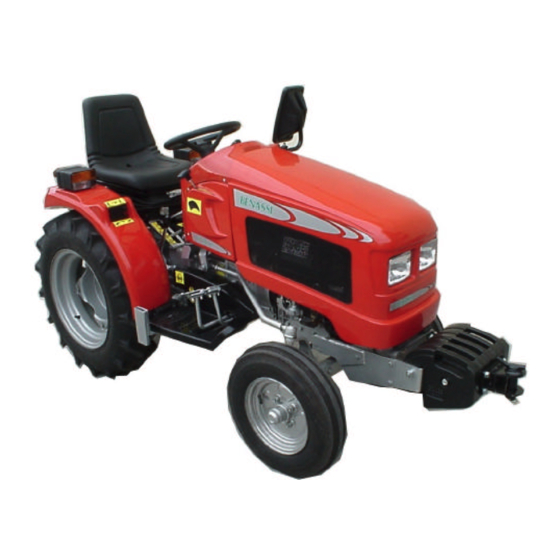
- Page 1 S.p.A. OPERATING AND MAINTENANCE MANUAL BT 2001 R Tractor Series 10/07/01...
- Page 2 Use genuine BENASSI products, spare parts and accessories. Any kind of modification or application not genuine will relieve BENASSI of any responsibility. The BENASSI Company declines all responsibility in cases of application to its machines o f accessories produced by other manufacturers, without authorisation.
-
Page 3: Table Of Contents
BT 2001 R S.p.A. CONTENTS: Safety rules and limits on use 16. Stopping the machine Instructions on tractor operation 17. Differential Lock Instructions on transporting and towing 18. Operating PTO shaft Use of tools 19. Use of the electric lift Technical data and characteristics 20. -
Page 4: Instructions On Tractor Operation
BT 2001 R S.p.A. Before starting the engine, make sure that the hand STARTING THE ENGINE brake is engaged, the clutch lever is down and the Read the operating and maintenance manual before control levers are disengaged. starting the engine Do not start the engine (by means of the key) if you are not seated at the driver’s seat. -
Page 5: Use Of Tools
BT 2001 R S.p.A. INSTRUCTION ON TRANSPORTING AND DRAWING The tractor is not permitted to tow any object with a weight exceeding the legal limit, on the road. Do not use the three-point linkage to tow. 4) USE OF TOOLS Keep hands and feet clear of implements fitted to the PTO shaft: danger of being dragged or crushed by moving parts. -
Page 6: General Dimensions And Weight
BT 2001 R S.p.A. BODYWORK Hinged bonnet, fixed arches for back wheels, adjustable FUEL seat with suspension. Tank capacity 6 litres Gearbox OIL ROTRA MP SAE 80W90: 12 litres. Oil Capacity of the engine (MD151): 1,8. Litres. ELECTRICAL SYSTEM The circuits used in the system, to power the electric horn and rotating light are fed by fuses type-tested for moving on the road. -
Page 7: Identification Of Safety Decals
BT 2001 R S.p.A. Left side Absorption coefficient plate engine plate Manufacturer plate Identifying number 8) IDENTIFICATION OF SAFETY DECALS IMPORTANT: To prevent accidents all decals fitted to the machine must be clearly visible. If decals become damaged replace them at once. - Page 8 BT 2001 R S.p.A. DIRECTION PLATES 1) DECAL: RIGHT FOOT POSITION WHEN NOT USING THE CLUTCH PEDAL 2) and 2a) DECAL: FOR CLUTCH “ENGAGEMENT-DISENGAGEMENT” 3) and 3a) DECAL: FOR ACCELERATOR “MIN - MAX” 4) DECAL: FOR GEARS 5) DECAL: FOR PTO SHAFT ENGAGEMENT-DISENGAGEMENT 6) DECAL: FOR 3 POINT-LINKAGE LIFTER, PLACED ON THE RIGHT WING 7) DECAL: FOR ABSORPTION COEFFICIENT, PLACED ON THE CHASSIS, NEAR TO THE MANUFACTURER PLATE.
-
Page 9: Identification Of Dashboard Controls
BT 2001 R S.p.A. 9) IDENTIFICATION OF DASHBOARD CONTROLS Fig. 3 Ignition Key. 11) Indicator stem, incorporating light switches and horn Hazard indicator switch. button. Main beam warning light (blue) Ο Ο Position Lights off Dipped beam warning light(green) Position... - Page 10 BT 2001 R S.p.A. 10) IDENDIFICATION OF THE MAIN PARTS AND CONTROLS Fig. 4 Fig. 5...
- Page 11 BT 2001 R S.p.A. Fig. 6 DESCRIPTION OF PARTS IN FIG. 4 WHEEL ARCH BONNET DIFFERENTIAL LOCK 10) ACCELERATOR LEVER LEFT BRAKE PEDAL 11) BONNET LIFTING POINT RIGHT BRAKE PEDAL 12) DASHBOARD BRAKE PEDAL LOCKING LEVER 13) SEAT ADJUSTMENT LEVER...
-
Page 12: Operating Controls
BT 2001 R S.p.A. 11) OPERATING CONTROLS Steering-wheel You can select 2 speeds in reverse gear (position 1 and 2) with one intermediate neutral position, See figure 5, point 11. Operates the rack steering gear to PARKING BRAKE. turn the front wheels. -
Page 13: Starting The Engine
BT 2001 R S.p.A. Fig. 5' Control for the Suspension longitudinal seat adjustment for adjustment. driver’s seat (movement of 60 weight (from 50 Kg. to 130 Kg.) mm.) 13) STARTING THE MOTOR Check the indicators and the control tools. Before starting, when the key is in the I position, check For information concerning the engine, read the that the indicators Ref.7 and Ref.8 (fig. -
Page 14: Setting The Machine In Motion
BT 2001 R S.p.A. 15) SETTING THE MACHINE IN MOTION Disengage the park brake, by releasing the lever Fig.6 Ref.5 Before moving forward, check the efficiency of Release the clutch pedal gradually (Fig.5 Ref.1) the brakes. Ø Accelerate by means of the lever Ref.10 Fig.4. -
Page 15: Use Of The Electric Lift
Press the switch (Ref.1 Fig.6) on its upper part to lift arms. Press the switch (Ref.1 Fig.6) on its lower part to lower arms. When you are not pressing the switch, the electric device is off but arms can be in their lifted position (BENASSI PATENT) -
Page 16: Use Of Towing Brackets
BT 2001 R S.p.A. 21) MOVING ON THE ROAD The tractor conforms to EC regulations, it can move on linkage”. Always remove the top link (ref.3 fig.9) if it is the road, if the following conditions are respected: not connected with any implement. -
Page 17: Use Of Ballast
BT 2001 R S.p.A. Fig.12 Fig.13 23) USE OF BALLASTS The use of ballast is necessary when the wheels slip due to insufficient adhesion to the ground. In this case, it is necessary to apply the metal modular weights Fig.13 Ref.1, which can be attached to the front bumper. -
Page 18: Periodical Maintenance
BT 2001 R S.p.A. FRONT AXLE ADJUSTMENT Track adjustment on the front axle allows 4 different widths, as shown in the preceding tables. To adjust the track, loosen and remove the nuts and bolts (2 on the left, Ref.1 fig.14 and 2 on the right, Ref.1 fig.15) adjust the axle. Replace the bolts in the appropriate position. - Page 19 BT 2001 R S.p.A. PERIOD PART OPERATION During first 50 hours (running in) • Diesel Engine Check the oil level • Wheels Check that wheel nuts are tight • • After first 50 hours (checking) Diesel Engine See the Manual •...
-
Page 20: Water Ballasting
BT 2001 R S.p.A. Drain plug is found underneath the gear box Oil used the PTO shaft, grease the relative joints, following Ø filler cap Ref.4 Fig.6 the instructions contained in the paper attached to this accessory. Greasing Every 50 hours grease the steering-gear box, by means Use AGIP GREASE LP2 grease. -
Page 21: Electrical System
BT 2001 R S.p.A. Fig.18 Fig.19 Ref. 1 Fig. 19 refers to the electrodes of the battery. 28) ELECTRICAL SYSTEM NOTE For information on the wiring diagram, contact the Technical Assistance Service. Battery: Read carefully the instructions supplied by the manufacturer. -
Page 22: Maintenance
BT 2001 R S.p.A. Fuse box: The fuse box is located under the steering wheel. Before changing a fuse, eliminate the problem that caused the short- circuit. The fuse wires protect the following electronic parts: FUSE POSITION DIAGRAM 7,5A 7,5A... - Page 23 BT 2001 R S.p.A. Lubricate all parts of the machine as indicated in the NOTE Ø If the period of non-utilisation becomes longer, recharge paragraph "PERIODICAL MAINTENANCE”. the battery periodically. Store the tractor in a dry well-ventilated place. If Ø...
- Page 24 BT 2001 R S.p.A. S.p.A. Via Lampedusa 1 I-40010 S. MATTEO DELLA DECIMA (BO) - ITALY TEL. 0039/051/820534 TELEFAX 0039/051/682.61.64 www.benassispa.it e-mail export@benassispa.it...