Table of Contents
Advertisement
SPLIT-TYPE, HEAT PUMP AIR CONDITIONERS
TECHNICAL & SERVICE MANUAL
Wall Mounted
Series PKFY
Indoor unit
[Model names]
PKFY-P20VAM-A
PKFY-P25VAM-A
INDOOR UNIT
R407C
[Service Ref.]
PKFY-P20VAM-A
PKFY-P25VAM-A
2001
R22
CONTENTS
1. SAFETY PRECAUTION ·····················3
2. PART NAMES AND FUNCTIONS······5
3. SPECIFICATION·································7
4. OUTLINES AND DIMENSIONS ·········9
5. WIRING DIAGRAM···························10
7. TROUBLESHOOTING······················12
8. DISASSEMBLY PROCEDURE·········17
9. PARTS LIST ·····································20
No. OC254
Advertisement
Table of Contents

Related Manuals for Mitsubishi Electric PKFY-P20VAM-A


Summary of Contents for Mitsubishi Electric PKFY-P20VAM-A
-
Page 1: Table Of Contents
SPLIT-TYPE, HEAT PUMP AIR CONDITIONERS No. OC254 TECHNICAL & SERVICE MANUAL Wall Mounted Series PKFY R407C Indoor unit [Model names] [Service Ref.] PKFY-P20VAM-A PKFY-P20VAM-A PKFY-P25VAM-A PKFY-P25VAM-A CONTENTS 1. SAFETY PRECAUTION ·····················3 2. PART NAMES AND FUNCTIONS······5 3. SPECIFICATION·································7 4. OUTLINES AND DIMENSIONS ·········9 5. -
Page 3: Safety Precaution
SAFETY PRECAUTION Cautions for using with the outdoor unit which adopts R407C refrigerant. · Do not use the existing refrigerant piping. -The old refrigerant and lubricant in the existing piping contains a large amount of chlorine which may cause the lubricant deterioration of the new unit. - Page 4 [1] Service tools Use the below service tools as exclusive tools for R407C refrigerant. Tool name Specifications Gauge manifold ·Only for R407C. ·Use the existing fitting SPECIFICATIONS. (UNF7/16) ·Use high-tension side pressure of 3.43MPa·G or over. Charge hose ·Only for R407C. ·Use pressure performance of 5.10MPa·G or over.
-
Page 5: Part Names And Functions
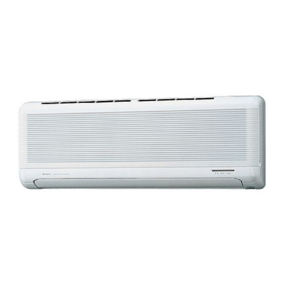
PART NAMES AND FUNCTIONS Indoor Unit PKFY-P20VAM-A PKFY-P25VAM-A Air intake Air intake grille Filter Auto Vane Guide vane Air Outlet MA remote controller [PAR-20MAA] Once the operation of the unit is set, subsequent operations can only be performed by pressing the ON/OFF button repeatedly. - Page 6 Display In this display example on the bot- CENTRALLY CLOCK display tom left, a condition where all dis- CONTROLLED display play lamps light is shown for expla- The current time , start time and stop time can be displayed in ten second nation purposes although this differs This indicates when the unit is con- intervals by pressing the time switch...
-
Page 7: Specification
SPECIFICATION 3-1. Specification Item Unit PKFY-P20VAM-A PKFY-P25VAM-A Single phase, 220-230-240V, 50Hz [,V,Hz Power Single phase, 220V, 60Hz Cooling capacity Heating capacity Cooling 0.04 Power Supply Heating 0.04 Cooling 0.20 Starting Current Heating 0.20 — Exterior <munsell symbol> Plastic munsell : <2.60Y 8.66/0.69>... - Page 8 3-2. Electrical parts specifications Model Symbol PKFY-P20VAM-A PKFY-P25VAM-A Parts name Room temperature TH21 Resistance 0:/15k", 10:/9.6k", 20:/6.3k", 25:/5.2k", 30:/4.3k", 40:/3.0k" thermistor Liquid pipe thermistor TH22 Resistance 0:/15k", 10:/9.6k", 20:/6.3k", 25:/5.2k", 30:/4.3k", 40:/3.0k" Gas pipe thermistor TH23 Resistance 0:/15k", 10:/9.6k", 20:/6.3k", 25:/5.2k", 30:/4.3k", 40:/3.0k"...
-
Page 9: Outlines And Dimensions
OUTLINES AND DIMENSIONS PKFY-P20VAM-A Unit : mm PKFY-P25VAM-A... -
Page 10: Wiring Diagram
WIRING DIAGRAM PKFY-P20VAM-A PKFY-P25VAM-A Legend Symbol Name Symbol Name Symbol Name Thermistor Pipe temperature,detection/Gas Indoor controller board TH23 Terminal Power supply CN32 Connector Remote switch (0:/15T,25:/5.4T) block Transmission HA terminal-A Circuit board CN41 Indoor power board Address board CN51 Centrally control Varistor SW1<A.B>... -
Page 11: Refrigerant System Diagram
Gas pipe temperature thermistor TH23 Gas pipe Flare Strainer (#50mesh) Liquid pipe temperature thermistor TH22 Liquid pipe Heat exchanger Linear expansion valve Strainer (#100mesh) Room temperature thermistor TH21 Models PKFY-P20VAM-A, PKFY-P25VAM-A Item Gas pipe {12.7 (1/2”) Liquid pipe {6.35 (1/4”) -
Page 12: Troubleshooting
TROUBLESHOOTING 7-1. How to check PKFY-P20VAM-A, PKFY-P25VAM-A Part Name Check points Room temperature Disconnect the connector, then measure the resistance using a tester. thermistor(TH21) (Surrounding temperature 10°C~30°C) Liquid pipe temperature thermistor(TH22) Normal Abnormal (Refer to the next page for a detail.) Gas pipe temperature 4.3k... -
Page 13: Linear Expansion Valve
<Thermistor Characteristic graph> < Thermistor for lower temperature > Room temperature thermistor(TH21) Thermistor for Liquid pipe temperature thermistor(TH22) lower temperature Gas pipe temperature thermistor(TH23) Thermistor R =15k' ± 3% Fixed number of B=3480k' ± 2% Rt=15exp { 3480( 273+t 15k' 9.6k' 6.3k' 5.2k'... - Page 14 <Output pulse signal and the valve operation> Output Output (Phase) Closing a valve : 1 Opening a valve : 4 The output pulse shift in above order. 1. When linear expansion valve operation stops, all output phase become OFF. 2. At phase interruption or when phase does not shift in order, motor does not rotate smoothly and motor lock, and vibrates.
-
Page 15: Function Of Dip Switch
7-2. FUNCTION OF DIP SWITCH PKFY-P20VAM-A, PKFY-P25VAM-A Operation by switch Switch Pole Function Remarks Thermistor<Intake temperature> Indoor unit Built-in remote controller Address board position Filter clogging Provide Not provide <At delivery> Filter sign indication 2,500 hr 100 hr 1 2 3 4 5 6 7 8 9 10... - Page 16 Switch Operation by switch Remarks Address board SW11 1st digit Address can be set while the address unit is stopped. SW12 SW11 setting Address setting should be done when M-NET <At delivery> SW12 remote controller is being used. SW12 SW11 2nd digit address setting...
-
Page 17: Disassembly Procedure
DISASSEMBLY PROCEDURE PKFY-P25VAM-A Be careful on removing heavy parts. PHOTOS & ILLUSTRATIONS OPERATION PROCEDURE 1. REMOVING THE LOWER SIDE OF THE INDOOR UNIT FROM Figure 1 Figure 2 THE INSTALLATION PLATE When there is removing plate (1) Remove the corner box at right lower side of the indoor unit. - Page 18 OPERATION PROCEDURE PHOTOS & ILLUSTRATIONS 3. REMOVING THE INDOOR MICRO CONTROLLER BOARD Electrical box cover Photo 2 AND INDOOR POWER BOARD (1) Remove the front panel. (Refer to 2) (2) Remove the electrical box cover (screw 4 10). (Refer to the photo 2) INDOOR MICRO CONTROLLER BOARD (1) Disconnect the following connectors on the indoor micro controller board.
- Page 19 OPERATION PROCEDURE PHOTOS & ILLUSTRATIONS 5. REMOVING THE NOZZLE ASSEMBLY Photo 5 (1) Remove the front panel (Refer to 2). Heat exchanger Electrical box (2) Remove the electrical box cover. (3) Disconnect the connector (CN5V) on the indoor micro con Drain hose troller board.
-
Page 20: Parts List
PKFY-P25VAM-A Part number that is circled is not shown in the figure. Q'ty / set Price Wiring Recom- Remarks No. Parts No. Parts Name Specifications PKFY-P20VAM-A Diagram mended Unit Amount (Drawing No.) Symbol Q'ty PKFY-P25VAM-A R01 22A 635 R01 22A 651... - Page 21 ELECTRICAL PARTS PKFY-P20VAM-A, PKFY-P25VAM-A CENTRALLY CONTROLLED 1Hr. ON OFF ˚C CLOCK CHECK FILTER CHECK MODE ˚C TEST RUN STAND BY ERROR CODE DEFROST NOT AVAILABLE FUNCTION TEMP. ON/OFF FILTER CHECK TEST TIMER SET PAR-20MAA 12 13 Q'ty / set Price...
- Page 22 HEAT EXCHANGER PARTS PKFY-P20VAM-A PKFY-P25VAM-A Q'ty / set Price Wiring Recom- Remarks No. Parts No. Parts Name Specifications PKFY- PKFY- Diagram mended Unit Amount (Drawing No.) P20VAM-A P25VAM-A Symbol Q'ty T7W E83 480 HEAT EXCHANGER With connection pipe T7W E84 480...
- Page 24 HEAD OFFICE : MITSUBISHI DENKI BLDG., 2-2-3, MARUNOUCHI, CHIYODA-KU TOKYO 100-8310, JAPAN cCopyright 2001 MITSUBISHI ELECTRIC ENGINEERING CO., LTD. New publication, effective Feb. 2001 Specifications subject to change without notice Distributed in Feb. 2001. No. OC254 785 Made in Japan...