Table of Contents
Advertisement
Quick Links
SERVICE MANUAL
General
Power requirements
Power consumption
Dimensions (approx.)
Mass (approx.)
Operating temperature
Operating humidity
System
Laser
Signal system
Frequency response
Signal-to-noise ratio
Harmonic distortion
Dynamic range
Outputs
VIDEO OUT
Audio output (digital audio)
Audio output (analog audio)
Accessory
Video cable . . . . . . . . . . . . . . . . . . . . . . .1
Audio cable . . . . . . . . . . . . . . . . . . . . . . .1
Remote control . . . . . . . . . . . . . . . . . . . .1
Batteries . . . . . . . . . . . . . . . . . . . . . . . . .2
• Design and specifications are subject to change without notice.
• Manufactured under license from Dolby Laboratories. Dolby and the double-D symbol are trademarks of Dolby
Laboratories. Confidential unpublished works. Copyright 1992-1997 Dolby Laboratories. All rights reserved.
• DTS and DTS Digital Out are trademarks of Digital Theater Systems, Inc.
SPECIFICATIONS
AC 110-240V , 50/60 Hz
14W
360 X 48 X 241 mm (w x h x d)
2.1 kg
5˚C to 35˚C (41˚F to 95˚F)
5 % to 90 %
Semiconductor laser, wavelength 650 nm
PAL/NTSC
DVD (PCM 96 kHz): 8 Hz to 44 kHz
DVD (PCM 48 kHz): 8 Hz to 22 kHz
CD: 8 Hz to 20 kHz
More than 100dB (ANALOG OUT connectors only)
Less than 0.008%
More than 100 dB (DVD)
More than 95 dB (CD)
1 Vp-p 75 Ω, sync negative, RCA jack x 1 / SCART (TO TV)
0.5 V (p-p), 75 Ω, RCA jack x 1
2.0 Vrms (1 KHz, 0 dB), 600 Ω, RCA jack (L, R) x 1 / SCART (TO TV)
XD-AX36
RM-Z401P
AEP Model
UK Model
CD/DVD PLAYER
Advertisement
Table of Contents

Related Manuals for Aiwa XD-AX36


Summary of Contents for Aiwa XD-AX36
-
Page 1: Specifications
XD-AX36 RM-Z401P SERVICE MANUAL AEP Model UK Model SPECIFICATIONS General Power requirements AC 110-240V , 50/60 Hz Power consumption Dimensions (approx.) 360 X 48 X 241 mm (w x h x d) Mass (approx.) 2.1 kg Operating temperature 5˚C to 35˚C (41˚F to 95˚F) - Page 2 WARNING!! Unleaded solder Boards requiring use of unleaded solder are printed with the lead- WHEN SERVICING, DO NOT APPROACH THE LASER EXIT WITH free mark (LF) indicating the solder contains no lead. THE EYE TOO CLOSELY. IN CASE IT IS NECESSARY TO (Caution: Some printed circuit boards may not come printed with CONFIRM LASER BEAM EMISSION, BE SURE TO OBSERVE the lead free mark due to their particular size.)
-
Page 3: Table Of Contents
TABLE OF CONTENTS GENERAL IC PIN FUNCTION DESCRIPTION Front Panel and Display Window ·············································· 1-1 5-1. DST/MPEG PIN FUNCTION (IC501:MT1379DEC) ···· 5-1 Remote Control ········································································· 1-1 Rear Panel ·················································································· 1-1 REPAIR PARTS LIST Connections ··············································································· 1-2 6-1. EXPLODED VIEWS ······················································ 6-1 Before Operation ·······································································... - Page 4 MEMO — 4 —...
-
Page 5: General
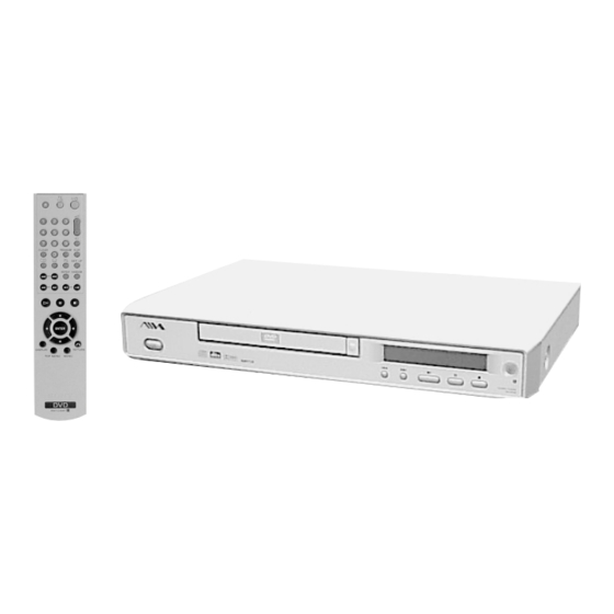
XD-AX36 SECTION 1 This section is extracted from GENERAL instruction manual. (9-885-044-58) Front Panel and Display Window @ / 1 Switches the player ON and OFF. Remote Sensor Power indicator Display window Lights green when the Shows the current status of the DVD player is turned on. -
Page 6: Connections
Connections Connections (Continued) Tips Connecting to Optional Equipment Depending on your TV and other equipment you wish Rear of DVD player Rear of TV to connect, there are various ways you could connect SCART INPUT Connecting to an amplifier equipped with two the player. -
Page 7: Operation With Dvd And Video Cd
Before Operation (Continued) Before Operation (Continued) Sound Others Parental Control Area Code Digital Audio Output Enter the code of a country/area whose standards were The DRC and PBC settings can be changed. Rating Press V/v to select the desired item and press used to rate the DVD video disc, referring to the list Each DVD disc has a variety of audio output options. -
Page 8: Operation With Audio Cd And Mp3 Disc
Operation with DVD and Video CD Operation with Audio CD and MP3 Disc Notes on MP3 Recordings Special DVD Features Playing an Audio CD and MP3 Disc About MP3 An MP3 file is audio data compressed by using the The DVD Player can play MP3 formatted recordings on Checking the contents of DVD Video MPEG1 audio layer-3 file-coding scheme. -
Page 9: Programmed Playback
Additional Information Programmed Playback VCD2.0 VCD1.1 Last Condition Memory Programmed Playback with Audio CD Programmed Playback with Video CD and MP3 Disc VCD1.1 Note The Program function enables you to store your favorite On a Video CD with PBC, you must set PBC to Off on the This player memorizes the user settings for the last disc tracks from any disc in the player memory. -
Page 10: Area Code List
Area Code List Enter the appropriate code number for the initial setting “Area Code” (See page 15). Code Area Code Area Code Area Code Area Andorra Eritrea Saint Lucia Seychelles United Arab Emirates Spain Liechtenstein Sudan Afghanistan Ethiopia Sri Lanka Sweden Antigua and Barbuda Finland... -
Page 11: Block Diagrams
XD-AX36 SECTION 3 BLOCK DIAGRAMS 3-1. OVERALL BLOCK DIAGRAM DISC DV33 DV33 DV33 DV33 IC502 IC503 IC506 IC5A1 HY57V161610DTC HY57V161610DTC M12L64164A 29LV800TA-70 512K 512K DVD:RF0,A,B,C,D CD:RF0,A,B,C,D,E,F 2Banks 2Banks 4Banks PICK SPINDLE MDI1 8BIT 16BIT 16BIT 16BIT LD01,LD02, IOA, V2.0 MOTOR... - Page 12 XD-AX36 MEMO 3-4E...
-
Page 13: Printed Wiring Boards And Schematic Diagrams
XD-AX36 SECTION 4 PRINTED WIRING BOARDS AND SCHEMATIC DIAGRAMS 4-1. SCHEMATIC DIAGRAM (1/5) SR14600A SCHEMATIC DIAGRAM (1/5) -
Page 14: Schematic Diagram (2/5)
XD-AX36 4-2. SCHEMATIC DIAGRAM (2/5) SR14601A SCHEMATIC DIAGRAM (2/5) -
Page 15: Schematic Diagram (3/5)
XD-AX36 4-3. SCHEMATIC DIAGRAM (3/5) SR14602A SCHEMATIC DIAGRAM (3/5) -
Page 16: Main Printed Wiring Board
XD-AX36 4-4. MAIN PRINTED WIRING BOARD (COMPONENT SIDE) MAIN... -
Page 17: Main Printed Wiring Board
XD-AX36 4-5. MAIN PRINTED WIRING BOARD (CONDUCTOR SIDE) MAIN 4-10... -
Page 18: Schematic Diagram (4/5)
XD-AX36 4-6. SCHEMATIC DIAGRAM (4/5) SCHEMATIC DIAGRAM (4/5) 4-11 4-12... -
Page 19: Boards
XD-AX36 4-7. TIMER & KEY, SW, SCART PRINTED WIRING BOARDS TIMER & KEY PRINTED WIRING BOARD SW PRINTED WIRING BOARD SCART PRINTED WIRING BOARD TIMER & KEY, SW, SCART 4-13 4-14... -
Page 20: Schematic Diagram (5/5)
XD-AX36 4-8. SCHEMATIC DIAGRAM (5/5) Note : The components identified by mark 0 or dotted line with mark 0 are critical for safety. SR16004C Replace only with part number specified. SCHEMATIC DIAGRAM (5/5) 4-15 4-16... -
Page 21: Power Printed Wiring Boards
XD-AX36 4-9. POWER PRINTED WIRING BOARD POWER 4-17 4-18... -
Page 22: Circuit Voltage Chart
XD-AX36 4-10.CIRCUIT VOLTAGE CHART IC201 IC202 IC501 IC502 IC503 IC505 IC510 IC5A1 IC601 IC602 IC604 IC201 IC202 IC501 IC502 IC503 IC505 IC510 IC5A1 IC601 IC602 IC604 (MT1336E) (MOTOR) (MT1379) (SDRAM) (SDRAM) (EEPROM) (BUFFER) (FLASH) (CS4391) (AMP) (MM1623XFBE) (MT1336E) (MOTOR) (MT1379) - Page 23 XD-AX36 IC201 IC202 IC501 IC502 IC503 IC505 IC510 IC5A1 IC601 IC602 IC604 IC201 IC202 IC501 IC502 IC503 IC505 IC510 IC5A1 IC601 IC602 IC604 (MT1336E) (MOTOR) (MT1379) (SDRAM) (SDRAM) (EEPROM) (BUFFER) (FLASH) (CS4391) (AMP) (MM1623XFBE) (MT1336E) (MOTOR) (MT1379) (SDRAM) (SDRAM) (EEPROM)
-
Page 24: Waveforms
XD-AX36 4-11.WAVEFORMS AV-079 IC201 IC202 IC501 IC502 IC503 IC505 IC510 IC5A1 IC601 IC602 IC604 BOARD (MT1336E) (MOTOR) (MT1379) (SDRAM) (SDRAM) (EEPROM) (BUFFER) (FLASH) (CS4391) (AMP) (MM1623XFBE) IC501 <z,n IC604 wd 4.0 Vp-p 2.6 Vp-p 37.0 ns IC604 qh IC604 wh 1.5 Vp-p... -
Page 25: Ic Pin Function Description
XD-AX36 SECTION 5 IC PIN FUNCTION DESCRIPTION 5-1. DST/MPEG PIN FUNCTION (IC501: MT1379DEC) Pin No. Pin Name Function IREF Current reference input PLLVSS – Ground pin for data PLL and related analog circuitry LPIOP Positive output of the low pass filter... - Page 26 Pin No. Pin Name Function IOA18 Flash address 18 / IO IOA19 Flash address 19 / IO IOA20 Flash address 20 / IO APLLVSS – Ground pin for audio clock circuitry APLLVDD3 – 3.3V power pin for audio clock circuitry Microcontroller address latch enable IOOE# Flash output enable, active low / IO...
- Page 27 Pin No. Pin Name Function DRAM data 8 DVSS – Ground pin for internal digital circuitry DRAM clock DRAM clock enable RA11 DRAM address 11 DRAM address 9 DRAM address 8 DMVDD3 – 3.3V power pin for DRAM clock circuitry DMVSS –...
- Page 28 Pin No. Pin Name Function ACLK Audio DAC master clock(384/256 audio sample freq.) MC DATA Microphone serial input SPDIF SPDIF output ASDATA0 Audio serial data 0 (Front L/R) ASDATA1 Audio serial data 1 (Rear L/R) ASDATA2 Audio serial data 2 (Center/Woofer) ASDATA3 Audio serial data 3 (Downmix L/R) ASDATA4...
- Page 29 Pin No. Pin Name Function IDGATE Header detect signal output DVDD3 – 3.3V power pin for internal digital circuitry UDGATE DVD_RAM recording data gate signal output WOBSI Wobble signal input SDATA RF serial data output SDEN RF serial data latch enable SCLK RF serial clock output Flag of defect data input status...
- Page 30 MEMO 5-6E...
-
Page 31: Repair Parts List
XD-AX36 SECTION 6 REPAIR PARTS LIST 6-1. EXPLODED VIEWS NOTE: • -XX, -X mean standardized parts, so they may • The mechanical parts with no reference number The components identified by mark 0 or have some differences from the original one. -
Page 32: Deck Mechanism Section
XD-AX36 6-1-2. DECK MECHANISM SECTION supplied supplied supplied supplied supplied supplied supplied supplied supplied supplied supplied supplied supplied supplied supplied supplied supplied Ref. No. Part No. Description Remarks Ref. No. Part No. Description Remarks 9-885-043-92 CABLE, FLAT 9-885-043-91 CABLE, FLAT... -
Page 33: Electrical Parts List
XD-AX36 6-2. ELECTRICAL PARTS LIST NOTE: • Due to standardization, replacements in the • RESISTORS When indicating parts by reference number, please include the board name. parts list may be different from the parts All resistors are in ohms. specified in the diagrams or the components... - Page 34 XD-AX36 Ref. No. Part No. Description Remarks Ref. No. Part No. Description Remarks <VIBRATOR> X501 9-885-040-11 CRYSTL ( 27MHz) X901 9-885-043-88 CERAMIC (6MHz) <VARISTOR> V101 9-885-035-07 VARISTOR SVC681D-10A ZD101 9-885-043-78 DIODE, ZENER GDZJ5.6B ZD102 9-885-043-76 DIODE, ZENER GDZJ3.3B ZD103 9-885-043-75 DIODE, ZENER GDZJ24B ZD510 9-885-043-78 DIODE, ZENER GDZJ5.6B...
- Page 35 XD-AX36 Sony Corporation 2003I1600-1 Home Storage Company 9-929-776-11 ©2003.9 — 50 — Published by Customer Support Div.