Axis 291 1U Installation Manual
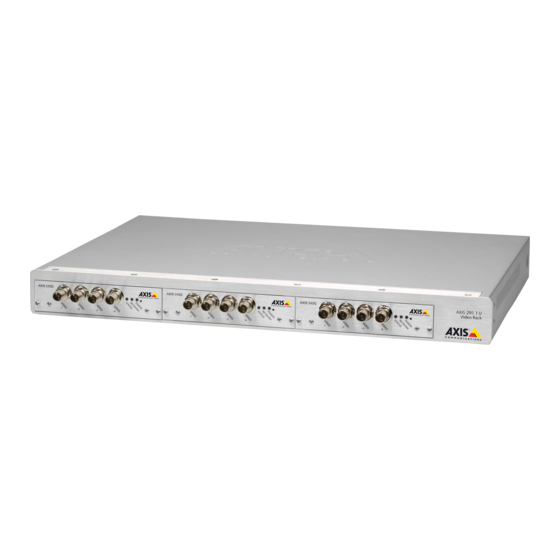
Video server rack
Hide thumbs
Also See for 291 1U:
- Installation manual (91 pages) ,
- Specifications (6 pages) ,
- Installation manual (51 pages)
Table of Contents
Advertisement
Quick Links
Download this manual
See also:
Installation Manual
Advertisement
Table of Contents

Related Manuals for Axis 291 1U


Summary of Contents for Axis 291 1U
- Page 1 INSTALLATION GUIDE AXIS 291 1U Video Server Rack...
-
Page 2: Axis Rack Mounted Video Server Solution
This installation guide describes the hardware installation of the AXIS 291 1U Video Server Rack, which can hold up to 3 Axis blade video servers. To install the Axis video server on the network, please see the video server’s own installation guide. -
Page 3: Axis 291 1U Video Server Rack - Overview
Network Connector - Axis blade video servers are designed for 10/100/1000 Mbps networks and are connected via a standard RJ-45 connector. Placement requirements The location the AXIS 291 1U Video Server Rack is used in must meet the following requirements: • Ambient temperature: 0° to +45°C (32° to 113°F) •... -
Page 4: Attaching The Brackets
The AXIS Video Server Rack must be grounded to the same ground as the equipment rack. When mounting the AXIS Video Server Rack in a rack, never stack other units directly on top - the mounting brackets are not designed to support more than 1 unit. Each unit in the rack must be secured with appropriate brackets. -
Page 5: Connect Power
Connect power The AXIS Video Server Rack has no On/Off switch or button and will power up as soon as the power cord is connected. Detaching the cord is the only way to remove power, so it is important to locate the unit so that the power cord is easily accessible. - Page 6 DIP Switches (4-port models) - Each video input has a corresponding line termination DIP switch. Axis blade video servers are supplied with the line termination enabled for each input; i.e. with the DIP switches set to ON (down position). To connect the video server in parallel with other equipment, disable the input termination by setting the corresponding DIP switch to OFF (up position).
-
Page 7: The I/O Terminal Connector
3. Fix the video server in place, using the screws from the front panel cover. Note: Leaving an empty slot on the AXIS Video Server Rack open is not permitted. Front panel covers must be used on all empty slots. -
Page 8: Connector Interfaces
4 Digital inputs - used for e.g. a pushbutton. If the button is pressed, the state changes • and the input will be active (shown under Event Configuration > Port Status). (AXIS 241Q Blade, AXIS 241S Blade, AXIS 243Q, AXIS 240Q) 4 Transistor outputs - for e.g. - Page 9 Assembly of multi-channel video server Serial numbers for each blade video server affixed here AXIS 291 1U Installation Guide v2.3 June 2009 Copyright © Axis Communications AB, 2007-2009 Part No. 35857...