Pioneer CDJ-2000NXS Service Manual
Multi player
Hide thumbs
Also See for CDJ-2000NXS:
- Operating instructions manual (47 pages) ,
- Quick start manual (44 pages) ,
- Quick start manual (116 pages)
Table of Contents
Advertisement
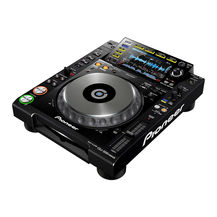
MULTI PLAYER
CDJ-2000NXS
THIS MANUAL IS APPLICABLE TO THE FOLLOWING MODEL(S) AND TYPE(S).
Model
Type
CDJ-2000NXS
UXJCB
CDJ-2000NXS
SYXJ8
CDJ-2000NXS
FLXJ
CDJ-2000NXS
AXJ5
CDJ-2000NXS
KXJ5
PIONEER CORPORATION
PIONEER ELECTRONICS (USA) INC. P.O. Box 1760, Long Beach, CA 90801-1760, U.S.A.
PIONEER EUROPE NV Haven 1087, Keetberglaan 1, 9120 Melsele, Belgium
PIONEER ELECTRONICS ASIACENTRE PTE. LTD. 253 Alexandra Road, #04-01, Singapore 159936
PIONEER CORPORATION
Power Requirement
AC 120 V
AC 220 V to 240 V
AC 110 V to 240 V
AC 220 V to 240 V
AC 220 V
1-1, Shin-ogura, Saiwai-ku, Kawasaki-shi, Kanagawa 212-0031, Japan
2012
CDJ-2000NXS
K-MZV SEPT.
ORDER NO.
RRV4356
Remarks
2012 Printed in Japan
Advertisement
Table of Contents

Related Manuals for Pioneer CDJ-2000NXS


Summary of Contents for Pioneer CDJ-2000NXS
- Page 1 PIONEER CORPORATION 1-1, Shin-ogura, Saiwai-ku, Kawasaki-shi, Kanagawa 212-0031, Japan PIONEER ELECTRONICS (USA) INC. P.O. Box 1760, Long Beach, CA 90801-1760, U.S.A. PIONEER EUROPE NV Haven 1087, Keetberglaan 1, 9120 Melsele, Belgium PIONEER ELECTRONICS ASIACENTRE PTE. LTD. 253 Alexandra Road, #04-01, Singapore 159936...
-
Page 2: Safety Information
For disposal or recycling information, please contact your local authorities or the Electronics Industries Alliance: www.eiae.org IMPORTANT Laser Pickup specifications and Laser characteristics THIS PIONEER APPARATUS CONTAINS For DVD Wave length (typ) : 655 nm LASER OF CLASS 1. Operation output : 3 mW CW, Class 1... -
Page 3: Table Of Contents
10.14 JFLB ASSY................................112 10.15 CDCB and SDSW ASSYS............................114 10.16 SLDB and EUPB ASSYS............................115 10.17 CNCT and KSWB ASSYS ............................116 10.18 JOGB and INDB ASSYS ............................117 10.19 POWER SUPPLY and ACIN ASSYS ........................118 10.20 WAVEFORMS................................. 120 CDJ-2000NXS... - Page 4 11.5 TFTB ASSY................................134 11.6 PNLB ASSY ................................138 11.7 JFLB, CDCB and SDSW ASSYS ..........................142 11.8 SLDB, EUPB and CNCT ASSYS ..........................146 11.9 KSWB, JOGB and INDB ASSYS ..........................148 11.10 POWER SUPPLY and ACIN ASSYS........................150 12. PCB PARTS LIST ................................152 CDJ-2000NXS...
-
Page 5: Service Precautions
FL Holder, attach a new JOG FL and an FL Holder, using two pieces of double-back tape, then mount them together. (Note: As the integrated JOG FL and FL Holder are exactly the same parts as those for the CDJ-2000, you can handle them in the same manner as with the CDJ-2000.) CDJ-2000NXS... -
Page 6: Service Notice
The settings can be stored for backup in a USB memory device or an SD card. For details on how to back up and restore data, see "g How to Back Up and Restore the Settings" in "8.5 ITEMS FOR WHICH USER SETTINGS ARE AVAILABLE ." CDJ-2000NXS... -
Page 7: Specifications
DVD test disc GGV1035 (DVDT-001) Drive self-diagnosis iPod cable GGP1201 For use in determining a cause of charging problem for an iPad DDE1142 (accessory for the CDJ-2000NXS) registered as a special tool Lubricants and Glues List Name Part No. Remarks Lubricating oil GYA1001 Refer to “9.3 CONTROL PANEL SECTION”,... -
Page 8: Check Points After Servicing
(This procedure can determine if the drive is degraded.) DVD test disc (GGV1025) See the table below for the items to be checked regarding audio. Item to be checked regarding audio Distortion Noise Volume too low Volume too high Volume fluctuating Sound interrupted CDJ-2000NXS... -
Page 9: Pcb Locations
2..SPCN ASSY DWX3336 1..USBB ASSY DWX3395 2..INDB ASSY DWX3337 > 1..POWER SUPPLY ASSY DWR1463 1..PNLA ASSY DWM2460 2..PNLB ASSY DWX3338 SLOTIN MECHA G11 ASSY DXA2163 2..KSWB ASSY DWX3339 TM ASSY 09SD -S DXX2697 2..SDSW ASSY DWX3340 2..EUPB ASSY DWX3341 CDJ-2000NXS... -
Page 10: Block Diagram
NEUTRAL(Blue) 100+/-3mm D K N 1 6 4 6 - A *VERTICAL DKP3935 ACIN ASSY LIVE USBB ASSY R T 2 LIVE(Brown) 112+/-3mm LIVE NEUTRAL LIVE EARTH NEUTRAL (DWX3346) NEUTRAL (DWX3395) NEUTRAL(Blue) 98+/-3mm CHASSIS EARTH (Green&Yellow Stripe) 63+/-3mm DKP3934 CDJ-2000NXS... - Page 11 The > mark found on some component parts indicates the importance of the safety factor of the part. Therefore, when replacing, be sure to use parts of identical designation. : The power supply is shown with the marked box. CDJ-2000NXS...
-
Page 12: Signal Block Diagram
IC301 CLK:48MHz DATA LRCLK IC12 IC13 IC302 32MB 32MB 32MB 32MB CLK:16.9344MHz USBB ASSY 32MB Core CLK:389.4912MHz SDRAM SDRAM SDRAM SDRAM FLASH SDRAM Bus CLK Bus CLK Bus CLK Bus CLK S/PDIF Bus CLK 107.86MHz 107.86MHz 107.86MHz 107.86MHz 129.8304MHz CDJ-2000NXS... - Page 13 FET AMP Universal OPAMP Host-Port Q503 IC502 Q518 Interface JA9402 U-HPI IC505 Analog out Analog Audio BCLK IC301 Q504 IC504 DATA Q505 IC503 Q517 CLK:16.9344MHz LRCLK CLK:16.9344MHz CLK:389.4912MHz JA9403 Q506 S/PDIF (Digital Audio) (fs=44.1kHz const.) Digital Audio Digital out CDJ-2000NXS...
-
Page 14: Power Supply Block Diagram
12V -> 5V V+3R3 V+3R3 P9402 IC9401 V-12 V+3R3 12V -> -12V V-12 V+1R2 V+1R2 IC705 V+1R2 12V -> 1.265V V+12_EUP MAIN ASSY CN702 CN6302 CN5102 USBB ASSY CN5101 IC6301 JA6301 V+5_USB SD Card Current USB-A Connector Detect Connector SDCB ASSY CDJ-2000NXS... - Page 15 V+3R3 P9201 IC9202 PNLB ASSY CN8501 12V -> AC2.7V V+1R2 CN4007 CN8002 JH8003 CN6201 V+12 V+12_EUP IC8002 INDB ASSY 12V -> 3.3V JH8701 V+3R3E CN8601 JH8001 JH8002 SDSW ASSY B ASSY SLDB ASSY CN8651 JA6301 USB-A EUPB Connector ASSY CDJ-2000NXS...
-
Page 16: Diagnosis
(IC7006) becomes "H". Communication between Main CPU and SRVO Communication between Main CPU and PNL CPU The insertion of the disk is possible. Communication between Main CPU and TFT CPU LED initial lighting Device select screen Canceling reset Apple authentication chip CDJ-2000NXS... -
Page 17: Failure Judgement Of The Pickup Assy
Disconnect* the FFC connected to the CN7001 then measure the resistance value between FFC pins 23 and 24. • Tracking side Disconnect* the FFC connected to the CN7001 then measure the resistance value between FFC pins 21 and 22. Failure judgment: A value out of the range of the specifications is judged as failure. CDJ-2000NXS... -
Page 18: Troubleshooting
Check that all the cables are securely Securely connect the cables. If a cable is broken, 4.1 OVERALL breakage, or connected. replace it. WIRING DIAGRAM loose connection Check that there is no breakage in the 10. SCHEMATIC of cables cables. DIAGRAM CDJ-2000NXS... - Page 19 TFT CPU. referring to [12-5] E-7023: GUI CPU ERROR. properly. • V+3R3T_BF, V+1R2_BF • RESET_TFT • BUSCLK (Approx. 98 MHz) Startup stops with the “Pioneer” logo displayed. Cause Diagnostics Point Item to be Checked Corrective Action Reference Communication...
- Page 20 Connect them properly or replace them. Defective PANEL PNLB Assy If the symptom persists after the above Check the connection of the PANEL CPU ————— corrections. (IC8003). If the connection is OK, the port may be damaged. Replace it. CDJ-2000NXS...
- Page 21 If there is any foreign object, the gears. remove it then replace the gears with new ones. After that, check that the JOG adjustment value is within the reference range, referring to “8.3 JOG DIAL ROTATION LOAD ADJUSTMENT.” CDJ-2000NXS...
- Page 22 The communication line may be loosely ————— in the USB signal. communication line (USB_D+, USB_D-). connected. Correct it if it is. Defective MAIN Assy If the symptom persists after the above The USB CONTROLLER (IC701) is defective. ————— USB CONTROLLER corrections. Replace it. CDJ-2000NXS...
- Page 23 If no problem is found, replace the transistor. If the SPDIF_OUT signal cannot be recognized, check the connection. If soldering is improper, resolder it. Defective MAIN Assy If the symptom persists after the above Replace the MAIN Assy. ————— MAIN DSP corrections. CDJ-2000NXS...
-
Page 24: Drive Assy
SODC (IC7006). Improper assembling Cables Check that the FPC cable that connects the If it does not, securely connect it. If it is broken, ————— traverse mecha and the SRVB Assy is replace the traverse mecha. securely connected. CDJ-2000NXS... - Page 25 Check the connections between pickup and CN7001 and IC7002. If soldering is improper, resolder it. If soldering is OK, replace the parts in the order of (1) FEP (IC7002), (2) DRIVER IC (IC7001), (3) SODC (IC7006), (4) SRVB Assy, then (5) traverse mecha. CDJ-2000NXS...
- Page 26 Defective SW ————— ————— The SW power is defective. Replace it. ————— power Reference: Signal logic during EUP mode Normal mode EUP mode EUP_CONT H or open PANEL CPU (IC8003) Pin 29 CPU_EUP_CONT X : Not Concerned CDJ-2000NXS...
- Page 27 FEP (IC7002). ————— ————— If the symptom persists after the above Replace the parts in the order of ————— corrections. (1) FEP (IC7002), (2) SODC (IC7006), (3) DRIVER IC (IC7001), (4) SRVB Assy, then (5) traverse mecha. CDJ-2000NXS...
- Page 28 Check the connections between MAIN DSP ————— between the MAIN MAIN DSP and SD_RAM. (IC301) and SD_RAM (IC302). DSP and SD_RAM If soldering is improper, resolder it. ————— ————— If the symptom persists after the above Replace the MAIN Assy. ————— corrections. CDJ-2000NXS...
- Page 29 Power is not TFTB Assy Check the power voltages of V+3R3T_BF The TFT CPU requires two power supply systems. ————— supplied properly. and V+1R2BF) lines. Check the connections of the power supply lines. If soldering is improper, resolder it. CDJ-2000NXS...
- Page 30 MAIN line between the MAIN CPU and (IC10) and AUTH CHIP (IC14). CPU and AUTH CHIP. If soldering is improper, resolder it. AUTH CHIP ————— ————— If the symptom persists after the above Replace the MAIN Assy. ————— corrections. CDJ-2000NXS...
-
Page 31: Operational Waveforms
Search (CD-DA/DVD-MP3) 1-ch TE, 2-ch TEDRV, 3-ch SLIN1, 4-ch SLIN2 Stop (CD/DVD) Setup (CD/DVD) 1-ch FE, 2-ch FEDRV, 3-ch TE, 4-ch SPIN 1-ch FE, 2-ch FEDRV, 3-ch SPIN, 4-ch SPDLFG Playback (CD/DVD) 1-ch FE, 2-ch TE, 3-ch SLIN1, 4-ch SLIN2 CDJ-2000NXS... -
Page 32: Setup Sequence
Tracking gain adjustment Focus gain adjustment Focus gain adjustment Focus position adjustment TOC (control data) Tr open reading Control data reading Acquisition of addresses Searching for the 1st piece of Searching for the top address music (SPDL acceleration starts) CDJ-2000NXS... -
Page 33: Connection Confirmation With The Pc
If the indication changes from 1 to 2 then 3, the link is properly established. If the cable is disconnected, the indication returns to 1. 5. After checking is completed, press the MENU/UTILITY key. The screen displayed before the MENU/UTILITY key was pressed will be restored CDJ-2000NXS... -
Page 34: Service Mode
When it spends a power supply while pushing a TEMPO button and a MEMORY button simultaneously, It is displayed in the LCD display part, "CDJ-2000NXS SERVICE MODE", and enters into this mode. (Please continue pushing until "Pioneer LOGO" screen disappears.) When it enters this mode, the TAG-TRACK button is pushed, and the screen is sent as follows, the following status displays are done. - Page 35 *1 About the LED of the HOT CUE button, red turns on HOT CUE(A), green turns on HOT CUE(B), and LED of the umber turns on HOT CUE(C). STANDBY-LED and DISC SLOT-LED are turned on only here. *2 A part of LED is turned on darkly. CDJ-2000NXS...
- Page 36 LCD as follows. If the BACK button is pushed, a display will return a previous page. Monochrome colorbar Colorbar Whole black screen Whole white screen Whole red screen Whole green screen Whole blue screen CDJ-2000NXS...
-
Page 37: Check Of Load Of Jog Dial
7.12 the name "JOGLOAD_2KNXS.CSV." 8.17 8.68 In addition, data is added whenever it pushes MASTER 8.17 TEMPO button. 8.54 Moreover, the MAC address is filled in as solid identification. 7.82 8.24 137(NG) (judge : 150ms <= Time <= 190ms) CDJ-2000NXS... -
Page 38: Indication Of Various Information
If a power supply is switched on, pushing "TEMPO" "CUE/LOOP CALL c" button simultaneously with a button, it will be displayed on LCD display part as "CDJ-2000NXS SERVICE MODE", and will go into this mode. (Please continue pushing until "Pioneer LOGO"screen disappears.) It goes into this mode, and if a TAG-TRACK button is pushed and a screen is sent, the contents of a display will change as follows. - Page 39 The state of the drive at the time of servo test operation and the measurement result of an error rate are displayed. Refer to "[7] A check of servo operation of a drive unit" for the details of operation. CDJ-2000NXS...
- Page 40 • Move the TEMPO slider • Touch the needle search ribbon • Switch the DIRECTION lever It will return from the auto standby mode. Since a return is the same processing as power supply ON, the service mode is ended. CDJ-2000NXS...
-
Page 41: Error Display List
When the communication with MAIN is not communicated. materialized by the abnormalities of connection, GUI displays an error code spontaneously. When MAIN does not operate completely, it will be in this mode. E-9101 MECHANICAL TIMEOUT Mechanism operation was not completed within regulation time. CDJ-2000NXS... - Page 42 OPTICAL SYSTEM DIRT CHECK CD ERROR RATE CHECK The following items are diagnosed. DVD-LD POWER CHECK DVD ERROR RATE CHECK The following items are diagnosed. USER CD PHYSICAL CHECK USER CD SCRATCH CHECK USER CD QUALITY CHECK USER CD DIRT CHECK CDJ-2000NXS...
- Page 43 (7000 H) is exceeded, time is displayed. (In within regulation time, OK is displayed and time is not displayed.) The worst value of the measured error rate is displayed in "CD Error Rate Check" and "DVD Error Rate Check". CDJ-2000NXS...
- Page 44 A, B, C, and D are measured by A/D, and it judges whether it is the level which can continue a playback. (9) OPTICAL SYSTEM DIRT CHECK Same as the above. (10) CD ERROR RATE CHECK An error rate is measured and the last check is performed. CDJ-2000NXS...
- Page 45 When a FWD direction was pushed with SINGLE LAYER DISC. → L0 inside → L0 middle → L0 outside → When a REV direction was pushed with SINGLE LAYER DISC. ← L0 inside ← L0 middle ← L0 outside ← CDJ-2000NXS...
- Page 46 It is indicated with [SLIDER FWD] in the indication part. Slider Move Rev You send about 1.8 mm sliders to an internal circumference direction whenever you push a SEARCH REV button. It is indicated with [SLIDER REV] in the indication part. CDJ-2000NXS...
- Page 47 Mode Change (The end of the test movement mode) If the MASTER TEMPO button is pushed into "test operation mode", MASTER TEMPO LED will light out, and it will shift to the above-mentioned "player operation mode." It is indicated with [PLAYER MODE] in the indication part. CDJ-2000NXS...
- Page 48 3 Auto device diagnosis of a "[3] Indication of various information", the test port output on a main board can also be checked. When a defect is detected by the device by power supply ON, an alarm port performs the following pulse outputs. CDJ-2000NXS...
- Page 49 2 Please turn on a power supply, pushing both the buttons of MEDIA SELECT/USB and RELOOP. (Please continue pushing until "Pioneer LOGO"screen disappears.) It is displayed the message of "Connect a USB storage device to the USB port.", USB memory is inserted in USB port of the front or the back.
- Page 50 When the message of "DRIVE firmware update failed." is displayed or the power supply has been turned off on the way, if a power supply is returned on again, the error code of "E-7001: DISC DRIVE ERROR" will be displayed. In such a case, the unit cannot be recovered by a retrial of downloading. Replacement of IC7004 (FLASH ROM) is required. CDJ-2000NXS...
-
Page 51: About The Device
SRVB Assy Contact position detection of a needle pad AD7147ACPZ500RL7 IC5001 CDCB Assy Two or more FLASH and SDRAM are mounted in the main body. Please diagnose it after confiming whether it is a device that agrees with purpose again. CDJ-2000NXS... -
Page 52: Disassembly
(2) Even if the unit shown in the photos and illustrations in this manual may differ from your product, the procedures described here are common. Diagnosis of SRVB Assy (1) Remove the two screws. Plate (BPZ30P100FTB) (2) Remove the five screws. (BPZ30P080FNI) (3) Remove the plate. Front • Bottom view Diagnosis SRVB Assy Front • Bottom view CDJ-2000NXS... - Page 53 (1) Remove the two screws. (BBZ30P060FTB) (2) Remove the five screws. (BPZ30P080FNI) Screw tightening order • Rear view The other screws are random order. Front • Bottom view • Bottom view (3) Remove the control panel section. Control panel section CDJ-2000NXS...
- Page 54 (5) Disconnect the two flexible cables. (CN702, 703) (6) Remove the three screws. CN703 (BBZ30P060FTB) CN702 Screw tightening order The other screws are random order. MAIN Assy Main cover (5) Stand the MAIN and JACB Assemblies. JACB Assy MAIN Assy Diagnosis CDJ-2000NXS...
- Page 55 • Be careful to the installation places. • Confirm it by viewing. This boss is not installation position. [2] Slotin Mechanism Section (1) Unhook the four hooks. (2) Release the jumper wires, as required. (3) Remove the slotin mechanism section. Slotin mechanism section CDJ-2000NXS...
- Page 56 After working, connect the flexible cable, then remove the soldered joint (open). for DVD for CD • Rear view (2) Disconnect the one connector and three SRVB Assy flexible cables. (CN7001, 7003, 7004, 7009) CN7003 CN7004 CN7001 CN7009 Front • Bottom view CDJ-2000NXS...
- Page 57 (DBA1260) (4) Remove the four float springs (G5). (5) Hook the four float springs G5 to the four hooks of the float base G11 Assy. Float base G11 Assy Float base G11 Assy Float spring G5 Float spring G5 CDJ-2000NXS...
- Page 58 SLMB Assy SPCN Assy [2] TM Assy-S (1) Remove the three float screws. SPCN Assy (DBA1286) (2) Remove the TM Assy-S. (3) Remove the one screw. (IPZ20P060FTC) (4) Unhook the two hooks. (5) Remove the SPCN Assy. TM Assy-S Front CDJ-2000NXS...
- Page 59 Pickup lens Reference information Screw tightening order (Stay/USB) Screw tightening order (SWPS stay) The other screws are random order. USBB Assy SD earth spring SDCB Assy Stay/USB • Bottom view SWPS stay Screw tightening order (Front plate) Front plate CDJ-2000NXS...
- Page 60 The other screws are random order. CN8801 JOG dial section CN8501 Front • Bottom view • Bottom view Position of the Adjust plate About details of Adjustment etc., refer to the “8.3 JOG DIAL ROTATION LOAD ADJUSTMENT”. Adjust plate • Bottom view CDJ-2000NXS...
- Page 61 (5) Unhook the three hooks. (6) Remove the JOG section. JOG section (7) Remove the three screws. (DBA1265) SW ring ×3 (8) Remove the SW ring. Note: Be careful not to lost SW spring. SW spring CDJ-2000NXS...
- Page 62 5. When making a connection, be sure to first release the lock of the connector then securely Holder/JOG relock the connector after making the connection. Holder/JOG Pasting position of the SW cushion HH48/2 SW cushion HH48/2 (×9) Sheet SW CDJ-2000NXS...
- Page 63 Rack plate Link gear A Reference information Screw tightening order (JFLB Assy) Screw tightening order (Stay Assy/JOG) The other screws are random order. JFLB Assy Barrier/JFL Stay Assy/JOG • Bottom view CDJ-2000NXS...
- Page 64 (CN4007, 4012, 8003, 8501, 8801) (7) Remove the one screw. (ABZ30P060FTC) (8) Remove the PNLB, EUPB, SLDB, KSWB, CN4007 CNCT and SDSW Assemblies by removing the 27 screws. (BPZ30P080FNI) CN4012 CN8003 CN8501 CN8801 Front KSWB Assy CNCT Assy SDSW Assy • Bottom view CDJ-2000NXS...
- Page 65 PNLB Assy EUPB Assy Front • Bottom view [2] Display Section (1) Remove the display section by removing the Display section eight screws. (BPZ30P080FNI) Screw tightening order The other screws are random order. • Bottom view • Bottom view CDJ-2000NXS...
- Page 66 • Bottom view Front lens Screw tightening order (CDC stay) • Bottom view The other screws are random order. CDC stay • Bottom view Screw tightening order (TFTB Assy) The other screws are random order. TFTB Assy • Bottom view CDJ-2000NXS...
-
Page 67: Each Setting And Adjustment
• TEMPO ZERO POINT ADJUSTMENT • JOG dial section component • JOG DIAL ROTATION LOAD ADJUSTMENT 8.2 FIRMWARE UPDATE / RECOVERY For details on updating of firmware and recovery of the main unit, see [9] UPDATING OF FIRMWARE in “6.1 SERVICE MODE.” CDJ-2000NXS... -
Page 68: Jog Dial Rotation Load Adjustment
Remove the screw fixing the adjust plate, then screw it into the hole corresponding to the value (-1, -2, -3, -4, +1, +2 or +3) for a load to be added: -1, -2, -3, -4 : To decrease the load +1, +2, +3 : To increase the load CDJ-2000NXS... -
Page 69: Tempo Zero Point Adjustment
Pin 4: ADIN J8705 J8704 Insulation sheet S8701 TEMPO RESET J8708 2 Match the knob section of slide VR with CENTER POSITION. Knob section of slide VR J8703 VR8702 (Zero Poin ADJ) C8702 VR8701 CENTER POSITION SIDE A SLDB ASSY CDJ-2000NXS... -
Page 70: Items For Which User Settings Are Available
1. Load/plug an SD card or USB memory device in which the settings are stored into this unit. 2. Press the device (SD or USB) button. 3. Press the MENU/UTILITY button. 4. Using the rotary selector, select and enter LOAD at MY SETTINGS. CDJ-2000NXS... - Page 71 CDJ-2000NXS...
-
Page 72: Exploded Views And Parts List
Screws adjacent to b mark on product are used for disassembly. For the applying amount of lubricants or glue, follow the instructions in this manual. (In the case of no amount instructions, apply as you think it appropriate.) 9.1 PACKING SECTION FLXJ Only SYXJ8 Only CDJ-2000NXS... - Page 73 NSP 13 License Key Label Assy DXA2190 NSP 14 Warranty See Contrast table (2) NSP 15 Leaflet See Contrast table (2) (2) CONTRAST TABLE CDJ-2000NXS/UXJCB, SYXJ8, FLXJ, AXJ5 and KXJ5 are constructed the same except for the following: CDJ-2000NXS CDJ-2000NXS CDJ-2000NXS CDJ-2000NXS CDJ-2000NXS Mark...
-
Page 74: Exterior Section
9.2 EXTERIOR SECTION Refer to “9.3 CONTROL PANEL SECTION”. TFTB CN4002 • Bottom view SLMB Stteping SPCN motor Pickup Refer to “9.6 SLOTIN MECHA SECTION”. UXJCB only AXJ5 only CDJ-2000NXS... -
Page 75: Exterior Section Parts List
27 Cushion/LAN DEC3431 28 Cushion/PCB DEC3455 29 Front Plate DNH2857 30 SWPS Stay DNH2890 (2) CONTRAST TABLE CDJ-2000NXS/UXJCB, SYXJ8, FLXJ, AXJ5 and KXJ5 are constructed the same except for the following: CDJ-2000NXS CDJ-2000NXS CDJ-2000NXS CDJ-2000NXS CDJ-2000NXS Mark Symbol and Description /UXJCB... -
Page 76: Control Panel Section
9.3 CONTROL PANEL SECTION • Bottom view Refer to "9.4 JOG DIAL SECTION". Refer to "9.5 DISPLAY SECTION". Lubricating oil (GYA1001) • Top view CDJ-2000NXS... -
Page 77: Control Panel Section Layout/Parts List
35 Ring Rens (PLAY) DNK5315 36 Tempo Lens DNK5316 37 Mode Lens DNK5317 38 Device Lens DNK5318 39 Front Lens DNK5328 40 Lever Cap DNK5344 41 Knob/SLD DNK5981 42 Control Panel DNK6030 43 Lens/EUP DNK6040 44 Cover/USB DNK6041 45 Button Assy/PLY DXB2126 CDJ-2000NXS... -
Page 78: Jog Dial Section
9.4 JOG DIAL SECTION Holder/JOG Lubricating oil (GYA1001) Lubricating oil (GEM1034) Lubricating oil (GEM1034) Lubricating oil Lubricating oil (GEM1034) (GEM1034) KSWB CN8501 CNCT CN8801 Lubricating oil (GYA1001) Lubricating oil (GYA1001) CDJ-2000NXS... - Page 79 DNK6143 31 Gear/B DNK6144 32 Leaf Spring/ADJ DBK1376 33 Barrier/JFL DEC3419 34 FFC/4P DDD1608 35 • • • • • 36 • • • • • 37 Screw (FE) DBA1265 38 Screw BPZ20P100FTC 39 Screw BPZ30P080FNI 40 Screw IPZ20P060FTC CDJ-2000NXS...
-
Page 80: Display Section
9.5 DISPLAY SECTION • Bottom view PNLB PNLB MAIN CN8002 CN8003 CN704 PNLB CN8001 CDJ-2000NXS... - Page 81 23 LCD Bottom Plate DNK5323 24 Reflector DNK5405 25 Cushion/FFC DEC3430 26 Barrier/RB DEC3421 27 Lens/CDC DNK6017 28 Rivet (Plastic) RBM-003 29 • • • • • 30 • • • • • 31 Screw BBZ26P060FTB 32 Screw BPZ26P080FTC CDJ-2000NXS...
-
Page 82: Slot In Mecha Section
9.6 SLOT IN MECHA SECTION Lubricating oil (GYA1001) SRVB CN7003 Lubricating oil (GYA1001) Dyfree Dyfree (GEM1036) (GEM1036) Lubricating oil (GYA1001) SRVB CN7001 Refer to “9.7 TM ASSY-S”. SRVB CN7004 SRVB CN7009 CDJ-2000NXS... - Page 83 DEC2852 30 Vessel Cushion B DEC2853 31 Vessel Cushion C DEC2854 32 Front Sheet DED1132 33 Inside SW Base DNK4236 34 Float Base G11 Assy DXB1793 35 Binder ZCA-SKB90BK 36 Float Fastener DBA1286 37 Screw VBA1062 38 Screw IPZ20P060FTC CDJ-2000NXS...
-
Page 84: Tm Assy-S
9.7 TM ASSY-S SRVB CN7004 Lubricating oil (GYA1001) Cleaning liquid (GEM1004) Cleaning paper (GED-008) SPCN CN6102 CDJ-2000NXS... - Page 85 5 Skew Spring DBH1437 6 Joint Spring (J) DBK1261 7 Slider Spring G11 (J) DBK1262 8 Guide Shaft (S) DLA1918 9 Joint DNK3858 NSP 10 Mounting Plate G11(J) DNK4307 11 Tapping Screw 04 VBA1092 12 Screw BPZ20P080FTC 13 Screw BPZ26P080FTC CDJ-2000NXS...
-
Page 86: Schematic Diagram
L T C 1 1 4 Y U B Q 7 0 0 3 C O N T N C 2 L T C 1 1 4 Y U B V I N V O U T 3.3V REG IC GNDSD GNDSA 1.5V DETECTING CIRCUIT GNDSA GNDSD CDJ-2000NXS... - Page 87 *RESISTORS : Tracking Servo Signal Route Indicated in Ω, ± 5% tolerance of identical designation. unless otherwise noted. k: kΩ, M: MΩ (SP) : Spindle Motor Signal Route (ST) : Stepping Motor Signal Route : Loading Motor Signal Route CDJ-2000NXS...
-
Page 88: Srvb Assy (2/2), Spcn, Insw And Slmb Assys
C T H 1 2 5 3 - A CN6302 V+5_USB_D GNDD GNDD CAUTION- FOR COTINUED PROTECTION AGAINST RISK OF FIRE. REPLACE WITH SAME TYPE No. 0437002. AND No. 0437.750 AND No. 04371.25 MFD. BY LITTELFUSE INC. FOR P7001 AND P7003 AND P7302 GNDD CDJ-2000NXS... - Page 89 LOADING MOTOR GNDSD re to use parts DXM1230- ZWNN1007G28-8-07A L=70mm GRAY Single Wire (SP) : Spindle Motor Signal Route : Loading Motor Signal Route AGAINST H SAME TYPE 0 AND FUSE INC. 7302 B C D CDJ-2000NXS...
-
Page 90: Main Assy (1/5)
IDED14_M SSICLK4 AUDIO_CLK4 IDED11_M IDED_10M IDED9_M IDED8_M IDE_INTM_M/ IDEIORDY_M/ IDED13_M/ IDED12_M/ 0.1u GNDD R 4 0 C S S 1 7 6 0 - A GNDD G N D 2 G N D 1 GNDD 48MHz V+3R3_CPU AlarmPort GNDD CDJ-2000NXS... - Page 91 GNDD C P U _ D S P _ E N A B L E 3:7D C P U _ P N L _ R S T C P U _ T F T _ R S T GNDD CDJ-2000NXS...
-
Page 92: Main Assy (2/5)
CPU_ADRS3 CPU_ADRS4 CPU_ADRS3 C 9 2 C 1 3 0 V D D 3 V S S 1 V D D 3 V S S 1 0.1u 0.1u M12L2561616A-5TG2A M12L2561616A-5TG2A GNDD GNDD CPU_ADRS_BUS 1:13B CPU_DATA_BUS_SDRAM CPU_DATA_BUS_SDRAM CPU_DATA_BUS_DSP *CAP *RES CDJ-2000NXS... - Page 93 CPU_DATA6D CPU_DATA6R CPU_DATA_BUS_R 5:1B CPU_DATA_BUS_DSP 3:2A NOTES means STANDBY RS1/16SS***J RS1/16SS****F *CAPACITORS Indicated in Capacity/Voltage(V) unless otherwise noted. u: μF, p: pF CKSSYB CCSSCH *RESISTORS Indicated in Ω, ± 5% tolerance CEHVAW221M6R3 unless otherwise noted. k: kΩ, M: MΩ CDJ-2000NXS...
-
Page 94: Main Assy (3/5)
K 1 1 C V D D 1 9 C V D D 2 0 L 3 0 4 R S V 1 C T F 1 5 7 9 - A R S V 2 3216size G N D D CDJ-2000NXS... - Page 95 RN1/16SE****D Indicated in Ω, ± 5% tolerance unless otherwise noted. k: kΩ, M: MΩ RS1/16SS****D RAB4CQ***J V + 1 R 2 _ D S P CKSSYB 9 - A CCSSCJ CFHXSQ CEHVAW 9 - A G N D D CDJ-2000NXS...
-
Page 96: Main Assy (4/5)
U S B 0 _ V D D A 1 8 U S B 0 _ D P USB2.0 U S B 0 _ V D D A 1 2 U S B 0 _ D M U S B 0 _ I D CDJ-2000NXS... - Page 97 μF, p: pF RS1/16SS***J : Analog Audio Signal Route *RESISTORS RN1/16SE****D Indicated in Ω, ± 5% tolerance : Digital Data Signal Route unless otherwise noted. k: kΩ, M: MΩ RS1/16SS****D RAB4CQ***J CKSSYB CCSSCJ CFHXSQ CEHVAW CDJ-2000NXS...
-
Page 98: Main Assy (5/5)
CN7301 *CAPACITORS V+3R3 RAB4CQ***J Indicated in Capacity/Voltage(V) V+3R3 unless otherwise noted. u: μF, p: pF CKSSYB or CKSRYB GNDD *RESISTORS CCSSCH or CCSRCH GNDD Indicated in Ω, ± 5% tolerance CEHVAW unless otherwise noted. k: kΩ, M: MΩ GNDD CDJ-2000NXS... - Page 99 The > mark found on some component parts GNDD GNDD GNDD indicates the importance of the safety factor of the part. Therefore, when replacing, be sure to use parts GNDD R 8 0 2 of identical designation. GNDD GNDD : pF M: MΩ CDJ-2000NXS...
-
Page 100: Jacb Assy
M: MΩ CCSRCH CAUTION : FOR CONTINUED PROTECTION AGAINST RISK OF FIRE. 2.0mm x 1.25mm size Chip ceramic capacitor REPLACE ONLY WITH SAME TYPE NO. 0437.750 MFD, BY LITTELFUSE INC. FOR P9401 and P9402. CEHAZL CDJ-2000NXS... - Page 101 R 9 4 1 2 CONTROL 4 7 0 R 9 4 1 7 2 7 0 D9405 NNCD6.2MF-TLB GNDD JA9403 DKB1113-A R 9 4 1 8 DIGITAL GNDD : Analog Audio Signal Route : Digital Data Signal Route CDJ-2000NXS...
-
Page 102: Sdcb Assy
R 5 1 2 0 R 5 1 2 2 L 5 1 0 1 V+3R3_SDM GNDD F5101 CCG1160-A GNDD V+3R3_SDM NOTES RS1/16SS***J RS1/10SR***J CKSSYB RN2903 Q5101 V+3R3 CN5102 GNDD V K N 1 4 1 4 - A CN702 CDJ-2000NXS... - Page 103 CDJ-2000NXS...
-
Page 104: Usbb Assy
USB_DN_B GNDD USB_DP_B GNDD R T 1 V_BUS_B USB_DN_B USB_DP_B D6302 R T 2 UMZU6.2N-TLB JA6302 D K N 1 6 4 6 - A GNDF GNDD USB CONNECTOR K N 6 3 0 1 (B-TYPE) Rating GNDF 1.5A CDJ-2000NXS... - Page 105 Therefore, when replacing, be sure to use parts of identical designation. RS1/16SS***J CTOR RS1/16SS****F RS1/10SR***J 1/10W *CAPACITORS CKSSYB Indicated in Capacity/Voltage(V) unless otherwise noted. u: μF, p: pF CCSRCH *RESISTORS Indicated in Ω, ± 5% tolerance unless otherwise noted. k: kΩ, M: MΩ CDJ-2000NXS...
-
Page 106: Tftb Assy (1/2)
1 0 0 TC7WHU04FK 9MHz D S S 1 1 6 4 - A GNDD *CAPACITORS Indicated in Capacity/Voltage(V) unless otherwise noted. u: μF, p: pF GNDD *RESISTORS Indicated in Ω, ± 5% tolerance unless otherwise noted. k: kΩ, M: MΩ CDJ-2000NXS... - Page 107 I C 4 0 1 8 T K 6 1 2 2 2 C Q 6 GNDD art. R 4 3 6 1 R 4 3 6 2 NOTES means STANDBY GND_BLP GNDD RS1/16SS***J RS1/16SS****D RS1/16SS****F RAB4CQ***J CKSSYB or CKSRYB CCSSCH or CCSRCH CEHVAW***M** CDJ-2000NXS...
-
Page 108: Tftb Assy (2/2)
1 0 0 p / 5 0 Q4035 C 4 2 3 4 1 0 0 p / 5 0 C 4 2 3 5 1 0 0 p / 5 0 GNDD RTQ045N03 CN4012 V K N 1 4 2 6 - A CN8001 CDJ-2000NXS... - Page 109 C 4 0 2 1 CPU_EUP_CONT GNDD EUP_CON GNDD V+12EUP KEY0 QUANTIZEL NEEDLEL V+12 V+3R3 CN4007 V+12 V K N 1 4 2 0 - A GNDD GNDD CN4015 V K N 1 4 0 9 - A CN8002 CN5002 GNDD CDJ-2000NXS...
-
Page 110: Pnlb Assy
D T H 1 2 1 2 - A J_DSO S U B 0.33m J_LAT J_LAT V O U T G N D J_BK J_BK JOGILM_W JOGILM_W BD45302G-TRB JOGILM_R JOGILM_R V+3R3 RESET IC GNDD GNDD GNDD GNDD 3.3V DCDC CON V+12 EUP (POWER STANDBY MODE) CIRCUIT GNDD CDJ-2000NXS... - Page 111 CKSRYB or CKSYB V O U T G N D Therefore, when replacing, be sure to use parts CCSRCH BD45302G-TRB of identical designation. CEHAS RESET IC CEHAZL GNDD GNDD CDJ-2000NXS...
-
Page 112: Jflb Assy
L T C 1 2 4 E U B V+3R3 means STANDBY GNDD RS1/10SR***J RN1/16SE****D GNDD RS1/8SQ***J JUMPER WIRE JH9201 JP9203:D20PDY1210E 5 1 0 4 8 - 1 2 0 0 RS1/4SA***J CKSRYB CCSRCH indic CEHAR CN8801 of id CEHAZL CDJ-2000NXS... - Page 113 Therefore, when replacing, be sure to use parts of identical designation. CAUTION : FOR CONTINUED PROTECTION AGAINST RISK OF FIRE. REPLACE ONLY WITH SAME TYPE NO. 0437001. MFD, BY LITTELFUSE INC. FOR P9201. CDJ-2000NXS...
-
Page 114: Cdcb And Sdsw Assys
S 8 6 0 1 S 8 6 0 2 USB ACCESS LED V S G 1 0 2 4 - A D S G 1 0 1 7 - A (RED) GNDD USB STOP SD-CARD SW Vf=2.2V If=1.3mA W=3.6mW CDJ-2000NXS... -
Page 115: Sldb And Eupb Assys
S L I - 3 4 3 U 8 R ( H J K ) R 8 6 5 1 EUPL C 8 6 5 1 EJECTL KEY4_B JH8002 GNDD EJECT NOTES 5 2 1 4 7 - 0 5 1 0 GNDD CN8651 means STANDBY RS1/10SR***J CDJ-2000NXS... -
Page 116: Cnct And Kswb Assys
D S G 1 1 1 7 - A 1 . 8 k C 8 5 0 2 GNDD GNDD V K N 1 2 6 4 - A V+12 CN8501 NOTES V+12 means STANDBY GNDD RS1/10SR***J CN6201 GNDD D_INDIL GNDD CDJ-2000NXS... -
Page 117: Jogb And Indb Assys
2 . 2 k D 6 2 0 1 R 6 2 0 1 GNDD 3 . 3 k GNDD CN8501 D_INDIL Q 6 2 0 1 L T C 1 1 4 Y U B LED lighting circuit GNDD NOTES RS1/10SR***J CDJ-2000NXS... -
Page 118: Power Supply And Acin Assys
T3.15AL 250V 220p D3SBA60 SFPL-52 R114 D101 0.22 220p C101 SCK15057M 0.0022 EXT41641-687C B2P3-VH-LF RC101 470k FME-220A C102 0.001 330/25V /25V 470k SARS04 MTZJ24B FMV13N60ES BAS21-03W KTA1666 100k EG01C SSC6210A UDZS20B BAS21-03W BAS21-03W 0.33 0.01 0.001 0.001 MTZJ30B PS2571-1 0.0022 CDJ-2000NXS... - Page 119 FME-220A C102 R105 PS2571-1 C103 R111 L101 /25V D102 /25V UDZS5.1B R106 R103 2.2k TCB-064 C104 R104 3.3k Q102 0.22 CN7302 R108 KTC3875 100k R113 Z101 STANDBY-CONTROL IN R112 4.7k RX102 R107 Q101 KRC122S D103 L103 UDZS15B GNDD FBR07VA121 CDJ-2000NXS...
-
Page 120: Waveforms
IC4 - pin 2 (TP) (USB_CLK) V: 1.0 V/div. H: 12.5 nsec/div. MODE: PLAY IC704 - pin 43 (ETH0_CLK2) V: 500 mV/div. H: 25.0 nsec/div. MODE: SD card PLAY CN702 - pin 6 (CPU_SD_CLK) V: 1.0 V/div. H: 20.0 nsec/div. CDJ-2000NXS... - Page 121 CDJ-2000NXS...
-
Page 122: Pcb Connection Diagram
C7013 C7138 65CHK VREF1 4.ST2- CN7004 3.ST2+ 2.ST1- C7142 Q7001 1.ST1+ V+5A C7028 C7030 C7132 VR65 IC7001 VR78 C7001 LD78 ST2+ LD65 C7010 ST1- C7002 C7026 ST1+ GNDSD R7014 CN7001 R7117 CONTACT R7015 R7025 SIDE DOWN 5 7 8 CDJ-2000NXS... - Page 123 C7009 C7115 2. View point of PCB diagrams. C7003 C7004 Connector Capacitor SIDE A R7014 C7036 CN7009 SIDE B R7118 P.C.Board Chip Part CONTACT C7109 R7024 C7025 SIDE DOWN LOAD VHALF R7015 C7024 (DNP2676-A) CDJ-2000NXS...
- Page 124 SIDE B SRVB ASSY CN7303 CN7301 CN700 (DNP2676-A) CDJ-2000NXS...
- Page 125 SIDE B CN7005 CDJ-2000NXS...
- Page 126 DWX3336- CN6102 CN6102 (DNP2676-A) CN6103 SPINDLE MOTOR INSW ASSY DWX3335- INSW CN6001 [[ G ]] A30C5 (DNP2676-A) SLMB ASSY SLOTSW S9001 CN9001 1.LO- 2.LO+ 3.GNDSD 4.LPS1 [[ G ]] 5.LPS2 SLMB S9002 DWX3345- (DNP2678-A) CN9001 CN7003 B C D CDJ-2000NXS...
-
Page 127: Spcn, Insw And Slmb Assys
11.2 SPCN, INSW and SLMB ASSYS SIDE B SPCN ASSY CN6102 CN6103 (DNP2676-A) INSW ASSY (DNP2676-A) SLMB ASSY S9001 SLOTSW CN9001 1.LO- S9002 2.LO+ 3.GNDSD SLOTSW 4.LPS1 5.LPS2 DWX3345- SOLDER SLMB CN9001 (DNP2678-A) B C D CDJ-2000NXS... -
Page 128: Main Assy
C733 D701 R728 C769 C739 IC704 C100 C732 C734 C770 C740 R825 L742 C761 R831 L701 C751 C748 R832 C108 R57 R58 L709 C759 0 1 2 3 0 1 2 3 4 5 6 7 8 IC704 IC102 CDJ-2000NXS... - Page 129 C534 R555 IC502 R553 R559 C551 R501 R554 R514 R515 Q513 Q502 Q507 R538 R532 1 2 3 4 5 6 7 8 9 R542 R550 (DNP2670-A) R552 C530 IC16 IC301 IC506 Q501 Q515 Q516 Q502 Q507-Q513 IC503 IC502 CDJ-2000NXS...
- Page 130 Q504 C131 C543 R782 C132 R779 R780 R781 R783 C518 R813 R516 R517 C519 R778 CN701 R520 C526 R582 [[ G ]] R521 A30C5 CN701 CN7005 IC302 Q517 Q505 IC505 IC12 IC13 IC504 Q520 Q506 Q519 Q503 Q518 Q504 CDJ-2000NXS...
- Page 131 IC10 R817 R824 R820 R745 R736 R759 R763 R761 R762 R760 C331 C332 C127 C333 C119 C311 C312 D702 R789 R790 R791 R116 R725 C753 C743 C762 R792 C754 R793 C757 CN705 (DNP2670-A) CN705 CN7301 IC701 IC11 IC10 IC705 CDJ-2000NXS...
-
Page 132: Jacb, Sdcb And Usbb Assys
JA9403 JA9401 JA9402 (DNP2678-A) SDCB ASSY JA6301 C6305 C6301 USBB ASSY R6307 C6304 R6301 R6304 R6302 KN6301 JA6302 C6310 C6308 R6306 C6309 IC6301 SDCB C6307 USBB CN5102 DWX3395- DWX3333- C5103 CN6302 CN5102 (DNP2695-A) (DNP2675-A) CN702 CN7303 F G H CDJ-2000NXS... - Page 133 [[ G ]] _DN_A 5,6,7.VBUS_A A30C5 C6303 CN6301 8.VB US_B C5106 C6311 9,11,13.GNDD Q5101 10.USB_DN_B R6303 L6301 12.USB_DP_B R5119 D6302 R5117 D5107 R5103 R5112 R5113 DWX3395- USBB R5115 R5116 R5104 R5111 R5106 R5108 R5109 CN6302 (DNP2675-A) CN5102 (DNP2695-A) F G H CDJ-2000NXS...
-
Page 134: Tftb Assy
C4227 Q4037 R4373 L4050 R4378 R4284 Q4038 CN4013 CONTACT C4222 R4390 SIDE R4391 DOWN R4007 IC4017 R4028 C4264 L4059 CN4013 CONTACT L4060 SIDE CN4007 C4280 C4279 CN4014 TFT-LCD MODULE R4400 C4268 L4058 R4407 C4269 CN4007 CN4014 CN8002 BACKLIGHT MODULE CDJ-2000NXS... - Page 135 PIN LIST R4296 21.PNL_BUSY CN8001 CN5002 ODULE 22.PNL_SCK 10.TFT_DATA1 1.TFT_PF1 23.PNL_CNVSS 11.TFT_DATA0 2.TFT_RST 24.USB_LED 12.V+1R2 25.USB_STOP 3.GNDD 13.V+3R3 4.TFT_RSCLK1 26.EUP_CONT 14.V+3R3 27.CPU_EUP_CONT 5.TFT_RFS1 15.V+5 6.TFT_DATA3 28.GNDD 16.V+12 7.GNDD 29.V+12_EUP 17.V+12 8.TFT_TSCLK1 18.PNL_RST 9.TFT_TFS1 19.PNL_RXD 20.PNL_TXD Q4041 C4287 C4021 (DNP2675-A) CDJ-2000NXS...
- Page 136 USB LED DWX3331- R4019 D4034 C4003 R4267 R4318 R4266 TFTB C4001 S4023 C4281 SD LED [[ G ]] IC4021 A30C5 C4008 D4037 C4241 C4242 CN4015 CN4012 S4024 DISC LED D4038 DISC QUANTIZEL_LED D4045 TIME_MODE AUTO_CUE S4029 S4020 QUANTIZEL (DNP2675-A) CDJ-2000NXS...
- Page 137 R4300 R4299 C4193 S4028 C4194 R4084 C4239 R4018 R4083 R4020 R4397 R4005 R4398 R4032 R4019 L4028 R4403 Q4001 R4389 4003 R4267 R4266 C4185 R4248 R4246 R4247 C4281 R4245 X4002 IC4021 C4016 R4014 C4011 L4053 D4031 CN4013 C4237 CN4007 CN4014 CDJ-2000NXS...
-
Page 138: Pnlb Assy
J8080 J8081 J8215 J8225 J8229 J8228 J8007 J8089 J8227 J8070 J8182 J8152 J8058 J8029 J8044 J8033 D8011 J8057 JUMPER J8146 J8098 J8175 J8038 J8181 T-SEARCH F J8079 J8088 J8077 J8051 J8194 J8180 T-SEARCH B J8177 SEARCH B SEARCH F CDJ-2000NXS... - Page 139 J8092 J8118 J8130 J8015 J8179 D8017 NO USE PNLB J8201 J8004 J8024 J8011 VINYL DWX3338- J8016 JOG MODE J8063 D8018 J8200 J8078 J8047 J8150 J8199 J8198 MASTER D8026 D8027 SYNC S8018 S8019 J8189 T.RANGE J8066 J8103 J8208 M.TEMPO (DNP2677-A) CDJ-2000NXS...
- Page 140 Q8020 [[ G ]] PNLB JOG MODE V+3R3E IC8006 Q8021 V+3R3E V+3R3E Q8024 Q8025 SYNC GNDD T.RANGE V+3R3E 1,V+5 2,GNDD 3,TRSTL 4,ADIN Q8019 5,ADCT 6,KEY3_B 7,GNDS 8,V+3R3E M.TEMPO IC8002 Q8023 IC8004 Q8018 Q8020 Q8017 IC8006 Q8025 Q8019 Q8024 Q8021 CDJ-2000NXS...
- Page 141 V+3R3 REC MODE V+3R3E SLIP GNDD Q8015 V+12 Q8015 GNDD GNDD GNDD Q8001 Q8012 GNDD GNDD GNDD T-SEARCH F V+3R3 IC8003 GNDD Q8016 V+12 T-SEARCH B 7.V+12 6.GNDD GNDD 5.CUEL 4.PLAYL 3.CUE 2.PLAY 1.D_INDL SEARCH F SEARCH B (DNP2677-A) CDJ-2000NXS...
-
Page 142: Jflb, Cdcb And Sdsw Assys
4.JOGILM_W J9224 GNDD 5.JOG_SW J9230 6.J_SCLK GNDD 7.J_LAT 8.J_BK J9223 J9213 9.J_DSO J9222 10.V+3R3 J9212 11.JOG1 J9233 12.JOG2 V+3R3FL J9231 GNDD J9226 V+3R3FL C9205 J9227 GNDD Q9201 Q9201 J9207 D9207 GNDD Q9202 Q9202 D9209 (DNP2678-A) CDCB A CDCB DWX3332- CDJ-2000NXS... - Page 143 GNDD D9205 CN4015 CDCB ASSY CN5002 Q5001 CONTACT SIDE R5008 CN5002 IC5001 L5002 3332- C5001 R5001 C5004 CN5001 R5004 L5004 C5006 [[ G ]] L5005 A30C5 C5003 L5003 R5003 CONTACT C5007 C5005 L5001 SIDE CN5001 (DNP2675-A) IC5001 Q5001 CN8003 CDJ-2000NXS...
- Page 144 Q9203 CN8601 SDSW DWX3340- Q8601 Q9204 USB STOP [[ G ]] (DNP2677-A) D9203 R9211 [[ G ]] R9244 Q9208 R9241 V+3R3FL R9242 R9214 R9213 R9208 GNDD R9212 R9207 V+3R3FL GNDD CDCB ASSY CN5002 CDCB DWX3332- CN5001 K L M CDJ-2000NXS...
- Page 145 Q9209 R9244 Q9207 Q9208 GNDD IC9204 Q9208 C9226 R9241 V+3R3FL R9242 C9223 C9224 R9214 R9209 C9222 C9225 GNDD R9248 R9250 R9249 R9203 R9202 R9201 R9204 V+3R3FL R9206 R9205 C9207 ADD SOLDER GNDD R9239 R9237 GNDD R9217 R9219 (DNP2678-A) (DNP2675-A) CDJ-2000NXS...
-
Page 146: Sldb, Eupb And Cnct Assys
J8818 S8701 JOGILM_R V+3R3 J8806 V+3R3 GNDD TEMPO RESET GNDD J8819 V+12 J8708 CN8801 1.V+12 2.GNDD 3.JOGILM_R 4.JOGILM_W 5.JOG_SW 6.J_SCLK 7.J_LAT 8.J_BK 9.J_DSO 10.V+3R3 11.JOG1 12.JOG2 (DNP2677-A) EUPB ASSY DWX3341- EUPB J8651 D8652 (DNP2677-A) S8651 N O P (DNP2677-A) CDJ-2000NXS... - Page 147 1.V+12 2.GNDD 3.JOGILM_R 4.JOGILM_W 5.JOG_SW [[ G ]] 6.J_SCLK 7.J_LAT 8.J_BK 9.J_DSO R8703 10.V+3R3 11.JOG1 12.JOG2 R8702 (DNP2677-A) SOLDER EUPB ASSY C8704 DWX3341- C8703 EUPB CN8651 1.EUPL R8652 2.EJECTL 3.KEY4_B (DNP2677-A) 4.GNDD 5.V+5 R8651 C8651 (DNP2677-A) N O P CDJ-2000NXS...
-
Page 148: Kswb, Jogb And Indb Assys
KSWB J8505 CN8502 DWX3339- J8502 CN8502 GNDD V+12 J8506 D8501 S8501 (DNP2677-A) PLAY JOGB ASSY INDB ASSY 1.GNDD 2.V+3R3 JOGB 3.JOG1 4.JOG2 DWX3337- INDB 1.V+12 2,3.GNDD 4.D_INDIL [[ G ]] DWX3349- A30C5 CN9301 D6201 (DNP2676-A) (DNP2678-A) Q R S CDJ-2000NXS... - Page 149 [[ G ]] Q8501 GNDD CN8502 CN8502 1.D_INDL 2.PLAY 3.CUE GNDD 4.PLAYL 5.CUEL V+12 6.GNDD 7.V+12 PLAY Q8502 (DNP2677-A) 4.V+12 3.GNDD 2.GNDD 1.D_INDL JOGB ASSY INDB ASSY DWX3349- JOGB C9301 R9303 R9302 C9302 6.GNDD R9301 5.VLED (DNP2676-A) (DNP2678-A) Q R S CDJ-2000NXS...
-
Page 150: Power Supply And Acin Assys
11.10 POWER SUPPLY and ACIN ASSYS SIDE A POWER SUPPLY ASSY ACIN ASSY AC INLET CN9101 CN9101 PRIMARY BLUE PURPLE ACIN (DNP2678-A) CDJ-2000NXS... - Page 151 SIDE B POWER SUPPLY ASSY ACIN ASSY CN9101 (DNP2678-A) CDJ-2000NXS...
-
Page 152: Pcb Parts List
SRVB ASSY R 7020,7117,7118 RS1/10SR1202F R 7021 RS1/10SR3302F SEMICONDUCTORS R 7042,7043,7063-7066 RAB4CQ101J IC 7001 BD7956FS IC 7002 AN22022A R 7057 RAB4CQ103J IC 7003 MM1478DFBE R 7088,7096,7302,7309 RS1/4SA0R0J IC 7004 DYW1816 R 7112,7334 RS1/10SR1002F IC 7005 S-1155B15-U5 R 7310 RS1/10SR2702D CDJ-2000NXS... - Page 153 CHOKE COIL CTH1487 C 7341 CKSRYB223K50 C 7342 CCG1221 L 710-742 FERRITE BEAD CTF1528 C 7359 CFHXSP104J16 F 2,3,701,705 EMI FILTER CCG1160 C 7360 CFHXSQ472J16 F 703 EMI FILTER DTL1106 JA 702 LAN JACK DKN1650 RESONATOR (48 MHz) CSS1760 CDJ-2000NXS...
- Page 154 R 9404 RN1/16SE1802D C 130,131,133,319 CKSSYB104K10 R 9405 RN1/16SE2201D C 132,325-337,732 CKSSYB102K50 R 9412 RD1/2VM471J C 134,514-517,532 CKSSYB222K50 R 9417 RD1/2VM271J C 301-316,343 CKSSYB103K16 Other Resistors RS1/10SR###J C 324,342,502,527 CKSSYB104K10 C 340,509,703,706 DCH1201 CAPACITORS C 341,717 CEHVAW101M6R3 C 9401,9404 CEHAZL101M25 CDJ-2000NXS...
- Page 155 R 4381 RS1/16SS5602D IC 4003 TC7WHU04FK R 4382 RS1/16SS3302D IC 4004 DYW1815 IC 4005 M12L2561616A-5TG2A R 4383 RS1/10SR0R0J IC 4017,4021 TC7SH08FUS1 R 4392,4411 RS1/10SR471J R 4412 RS1/10SR822J IC 4018 TK61222CQ6 Other Resistors RS1/16SS###J IC 4019 NJM2887DL3 Q 4001 LSCR523UB CDJ-2000NXS...
- Page 156 S 8001-8004,8008 SWITCH VSG1024 MISCELLANEOUS L 9201 POWER INDUCTOR DTL1187 S 8005-8007,8010-8012 TACT SWITCH DSG1079 V 9201 FL INDICATOR TUBE DEL1058 S 8009,8020 TACT SWITCH DSG1089 T 9201 POWER TRANSFOMER DTT1232 S 8013-8019,8021,8022 SWITCH VSG1024 CN 9203 CONNECTOR CKS1072 CDJ-2000NXS...
- Page 157 Other Resistors RS1/16SS###J KSWB ASSY CAPACITORS SEMICONDUCTORS C 5001 CKSSYB103K16 Q 8501,8502 LTC114YUB C 5002 CKSSYB104K16 D 8501 SLR343EC4T(LMN) C 5003 DCH1201 D 8502 SLI-343Y8Y(KLM) C 5004-5008 CCSRCH101J50 MISCELLANEOUS S 8501,8502 TACT SWITCH DSG1117 CN 8501 4P CONNECTOR VKN1264 CDJ-2000NXS...
- Page 158 CN 6201 04P CONNECTOR RKN1045 RESISTORS All Resistors RS1/10SR###J POWER SUPPLY ASSY There is no service parts. AC IN ASSY MISCELLANEOUS S 9101 SWITCH DSA1037 CN 9101 AC CODE SOCKET RKP1751 JP 9101 CONNECTOR ASSY2P DKP3822 CAPACITORS C 9102 ACG7030 CDJ-2000NXS...