Advertisement
Quick Links
AM-RGR
Remote
Receiver
Installation
Instructions
(760) 438-7000 • FAX (760) 438-7043
USA & Canada (800) 421-1587 & (800) 392-0123
Toll Free FAX (800) 468-1340
www.linearcorp.com
2. OPEN CASE
BOARD SLIDES OUT
FROM 3RD SLOT UP
INSIDE CASE
REMOVE FOUR
SCREWS AND WASHERS
INTRODUCTION
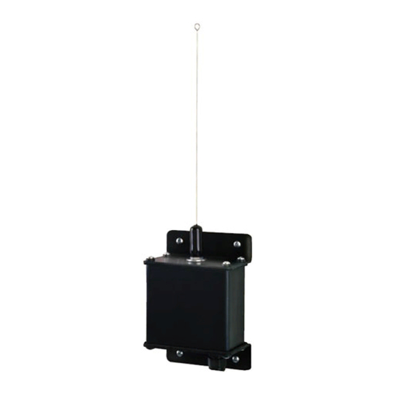
The AM-RGR remote radio receiver is designed for use with Linear's Model
AM/II access control system. The AM-RGR functions as a remote device that
supports reception of Linear's GT-30 and GT-31 transmitters.
Three antenna types can be used with this receiver. The enclosure mounted
type "F" connector is for connection to the antenna. The local whip antenna
(supplied) screws directly on to the receiver's connector. The directional
(EXA-2000) and omni-directional (EXA-1000) remote antennas wire to the
receiver's antenna connector with type RG-59 cable.
An on-board RADIO RANGE knob allows adjustment of the receiver's range.
It can be set to limit the maximum radio range that the receiver can achieve.
Two indicators display the receivers performance and operation. The two color
red/green STATUS indicator lights red when the receiver is getting DC power
and turns green when access is granted to a transmitter. The RADIO indicator
lights when the receiver detects a radio signal. It can be used for
troubleshooting and verifying system performance. Receiver test points are
provided for listening to the incomming signals.
The AM-RGR remote radio receiver connects to the AM/II control unit through
a six-wire cable. A rotary switch in the AM-RGR selects the device address
for the receiver. Each remote device must be set to a different device address.
Power is supplied to the receiver from the AM/II.
The receiver is housed in a weather-resistant enclosure and can be mounted
indoors or outdoors. Gaskets and a weather-tight wiring strain relief seal the
unit from the elements.
3. LOCATE COMPONENTS
RADIO
RANGE
OPEN CASE FROM
KNOB
ANTENNA END
CLOCKWISE
FOR MAXIMUM
RANGE
GND
AUDIO
RADIO
TEST
POINTS
RADIO
INDICATOR
ANTENNA
CONNECTOR
(HIDDEN)
DEVICE
ADDRESS
SELECTOR
POWER & DATA
TERMINALS
STATUS
(CONNECTS TO AM/II)
INDICATOR
RED = POWER
GREEN = ACCESS
1. TYPICAL INSTALLATION
CABLE RUN
CABLE TYPE
300 FEET MAXIMUM
BELDEN 9931 (24 AWG)
FEET x LOAD UNITS < 3,000 MAXIMUM
500 FEET MAXIMUM
WEICO 9405 (20 AWG)
FEET x LOAD UNITS < 10,000 MAXIMUM
4. SET DEVICE ADDRESS
FORMULA
Advertisement

Related Manuals for Linear AM-RGR

Summary of Contents for Linear AM-RGR
-
Page 1: Installation Instructions
The AM-RGR remote radio receiver connects to the AM/II control unit through a six-wire cable. A rotary switch in the AM-RGR selects the device address for the receiver. Each remote device must be set to a different device address. - Page 2 Consumers should inquire from their selling dealer as to the nature of the dealer’s warranty, if any. There are no obligations or liabilities on the part of Linear Corporation for consequential damages arising out of or in connection with use or performance of this product or other indirect damages with respect to loss of property, revenue, or profit, or cost of removal, installation, or reinstallation.