Linear Security DUAL 824 Installation & Programming Instructions
Supervised wireless security control panel
Hide thumbs
Also See for Security DUAL 824:
- Installation instructions manual (48 pages) ,
- Quick reference manual (2 pages)

Related Manuals for Linear Security DUAL 824

Summary of Contents for Linear Security DUAL 824
- Page 1 DUAL 824 SUPERVISED WIRELESS SECURITY CONTROL PANEL Installation & Programming Instructions USA & Canada (800) 421-1587 & (800) 392-0123 (760) 438-7000 - Toll Free FAX (800) 468-1340 www.linearcorp.com...
- Page 2 INTRODUCTION CONGRATULATIONS for selecting Linear's DUAL 824 Security System. The Model DUAL 824P Control Panel and the Model DUAL 824KP Keypad incorporate many advanced and sophisticated features. The system can be expanded and customized to fi t the installation's specifi c needs.
-
Page 3: Table Of Contents
LINEAR LIMITED WARRANTY ........ -
Page 4: The Dual 824 Security System
Automation Output. The Control Panel can be programmed locally using its own keypad or remotely, over the telephone, using Linear's Model RA-2400 Remote Access software program. The RA-2400 upload/download program is a Windows... -
Page 5: Door/Window Sensors
DOOR/WINDOW SENSORS The DXS-31 and DXS-32 sensors monitor doors and windows. They send radio signals to the Control Panel. One type of signal is sent when the door or window is opened, and a different type of signal is sent when the door or window is closed. If the system is armed, a sensor can trigger the Control Panel's burglary siren when its door or window is opened. -
Page 6: Security System Floor Plan
SECURITY SYSTEM FLOOR PLAN EXAMPLE SYSTEM ✦ The example shows a typical DUAL 824 system. ✦ Any or all of the accessories shown can be used. ✦ A total of 24 sensors can be used with each Control Panel. Each wireless sensor, hardwired loop, and wireless keypad used occupies a sensor location. -
Page 7: Overview Of Keypads
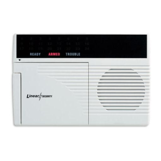
OVERVIEW OF KEYPADS HARDWIRED KEYPAD ✦ One or two hardwired keypads can be used for controlling the system. ✦ Three system status indicators: READY, ARMED, & TROUBLE ✦ Three system supervisory indicators: POWER, BATTERIES, & RADIO ✦ Five system mode indicators: OFF, CHIME, HOME, AWAY &... -
Page 8: Hardwired Keypad Features
HARDWIRED KEYPAD FEATURES BEAUTY COVER ★ The beauty cover snaps open and shut to hide the keypad’s keys, mode and supervisory indicators, and the sensor location labeling area. KEYPAD ★ Backlit keys for easy viewing in low light conditions. ★ For entering the user's user code (numerically or alphabetically). ★... -
Page 9: Control Panel Features
★ A cabinet knockout is provided for mounting an external antenna connector. ★ For an external antenna, use Linear's Model LA-P antenna kit. ★ The antenna kit can also be used to connect the Control Panel to co-ax for a remote antenna. -
Page 10: Control Panel Installation
4. Use four screws and appropriate screw anchors to mount the unit to the wall. EXTERNAL ANTENNA ✦ Linear's Model LA-P antenna kit can be used with the DUAL 824P Control Panel to replace the standard internal antenna. ✦ The antenna can be mounted on the cabinet, or the kit can be used to connect to co-ax for a remote antenna. -
Page 11: Hardwired Keypad Installation
HARDWIRED KEYPAD INSTALLATION ✦ One or two Model DUAL 824KP keypads can be used with the DUAL 824P Control Panel (one keypad is included in the DUAL 824 system package). ✦ The keypad is supplied with a short wiring harness and connector. -
Page 12: Hardwired Loop Wiring
HARDWIRED LOOP WIRING ✦ The DUAL 824 supports up to eight normally open/closed hardwired loops each with 2.2K end-of-line resistor supervision. ✦ Each hardwired loop that is wired and programmed uses one sensor location. ✦ Each hardwired loop can be programmed to any sensor number. -
Page 13: External Alarm Siren Connection
5. Connect the local telephone set wires to the Control Panel's telephone terminal block T1 and R1 terminals. ✦ When directly connecting (without a telephone line) to the DUAL 824 with the RA-2400 remote access software (Version 1.3 or later), disconnect the incoming telephone line and connect the modem to the panel's TIP and RING terminals (with the modem's red &... -
Page 14: Automation Output Connection
H/A + H/A - POWER SOURCE LIGHT EMITTING DIODE (L.E.D.) YOUR LOAD LINEAR RB-90 RELAY MODULE VB-2 VOICE RESPONSE MODULE MICROPHONE #2 (+) MICROPHONE COMMON (-) MICROPHONE MICROPHONE #1 (+) TERMINALS MODULE-TO-CONTROL PANEL CONNECTOR BE SURE CONTROL PANEL POWER IS DISCONNECTED! -
Page 15: Control Panel Power Connection
CONTROL PANEL POWER CONNECTION ✦ The Control Panel is powered by a low voltage plug-in transformer. ✦ Use up to 25 feet of 20 AWG or larger 2-conductor wire to connect the transformer to the Control Panel. 1. Route the power wires from the plug-in transformer to the Control Panel. -
Page 16: Basic Control Panel Programming
BASIC CONTROL PANEL PROGRAMMING ✦ In a new installation, when power is fi rst applied the system's master user code is “1234”. CREATE THE MASTER USER CODE ✎ NOTE: Local programming must be entered on the system's hardwired keypad, not on a wireless keypad. -
Page 17: Program The Hardwired Loops
PROGRAM THE HARDWIRED LOOPS ✦ Each hardwired loop used must be programmed into the Control Panel's memory. ✦ Each hardwired loop programmed uses one of the twenty four available sensor locations. 1. Start with the system in Test Mode (enter the master user code and press TEST). -
Page 18: Programming Different Sensor Types
PROGRAMMING DIFFERENT SENSOR TYPES ✦ Follow the instructions on the previous page to select a sensor number to program the sensor into. ✎ NOTE: A sensor can be programmed into more than one location. Be sure to choose an UNUSED sensor number. - Page 19 PROGRAMMING DIFFERENT SENSOR TYPES (CONT.) ✦ For DXT-61, DXT-21, DXS-21, DXT-41, & DXS-62A single-button remotes, simply press the unit's button. ✎ NOTE: After the Control Panel recognizes the transmitter, single-button remotes must be re-programmed as “panic buttons” or home automation controllers. Refer to Page 28 in the “Customizing the System”...
-
Page 20: Basic Sensor Installation
✦ Refer to the sensor's instructions for details on installing, operating, and testing of the sensor. ✦ Following are basic instructions for installing two popular DUAL 824 accessories: The Model DXS-10 Wireless Remote Keypad and the Model DXS-31 & DXS-32 Door/Window Transmitters. DXS-10 WIRELESS KEYPAD ✦... -
Page 21: Dxs-31 & Dxs-32 Door/Window Sensors
DXS-31 & DXS-32 DOOR/WINDOW SENSORS ✦ The DXS-31 and DXS-32 sensors can be used to monitor doors, windows, cabinets, crawl space doors, gates, freezer doors, and many other moving objects that could be used for intrusion or need to be monitored. ✦... -
Page 22: Customizing The Keypad
CUSTOMIZING THE KEYPAD ✦ The system can be customized for the specifi c installation. ✦ A label sheet with sensor location names is provided with DUAL 824KP keypads. ✦ Labeling the sensors allows quick and easy identifi cation of where a door or window is open, where any alarms have occurred, where a sensor with a low battery is, or where a sensor with trouble is. -
Page 23: 10. System Operating Modes
10. SYSTEM OPERATING MODES OFF MODE ✦ Use this mode to disarm the burglary portion of the system. ✦ The 24-hour functions are still active in Off Mode and can be triggered with wireless or hardwired sensors, or by pressing the FIRE or EMERGENCY on the keypad(s). -
Page 24: Home Mode
HOME MODE ✦ Use this mode when sleeping or when anyone is staying inside. ✦ Home Mode causes an instant alarm when any perimeter sensor is triggered. ✦ Home Mode causes a delayed alarm when any exit/entry sensor is triggered (except in Home Instant Mode when they are instant). -
Page 25: Away Mode
AWAY MODE ✦ Use this mode when no one will be staying home. ✦ Away Mode causes an instant alarm when any perimeter sensor is triggered. ✦ Away Mode causes a delayed alarm when any exit/entry sensor is triggered. ✦ Away Mode causes an instant alarm when any interior sensors (motion detectors, etc.) are triggered. -
Page 26: Test Mode
Mode, it will automatically switch back to Off Mode after three minutes. ✦ When directly connecting (without a telephone line) to the DUAL 824 with the RA-2400 remote access software (Version 1.3 or later), press the EMERGENCY key while in Test Mode to cause the control panel to connect to the modem. -
Page 27: 11. System Trouble Indications
11. SYSTEM TROUBLE INDICATIONS ✦ The DUAL 824P Control Panel is a self- monitoring supervised wireless system. If the Control Panel detects a problem with any of the supervised system sensors or with its power, it will display the appropriate trouble indication and, if monitored, report the trouble to the Central Station through the communicator (depending on communicator programming). -
Page 28: 12. Customizing The System
12. CUSTOMIZING THE SYSTEM ✦ Adding additional sensors will increase the protection provided by the system. ✦ All ground-level perimeter openings and accessible upper-story openings need protection. ✦ Motion detectors can protect interior areas and areas where valuables are kept. ADDING SENSORS TO THE SYSTEM 1. -
Page 29: Making A Sensor A 24-Hour Door Chime
MAKING A SENSOR A 24-HOUR DOOR CHIME ✦ Sensors can be programmed to cause the keypad(s) to chime any time they're activated. ✦ Chime-only sensors will not be able to trigger the alarm in any system mode. ✦ The sensor must have already been programmed into the Control Panel (see “Adding Sensors to the System”... -
Page 30: Making A Sensor Perform A Different Function
MAKING A SENSOR PERFORM A DIFFERENT FUNCTION ✦ Sensors can be reprogrammed to perform different sensor functions. ✦ The sensor must have already been programmed into the Control Panel (see “Adding sensors to the System” for details). 1. Start with the system in Test Mode. 2. -
Page 31: 13. Advanced Programming
13. ADVANCED PROGRAMMING ✦ To perform any of the advanced programming steps, the system must be in the Setup Mode. ✦ Each programming function is performed with similar keystrokes. After the system is in Setup Mode, enter the programming step or sensor number and press HOME, then enter the new value and press AWAY. -
Page 32: Changing A Sensors Supervision
CHANGING A SENSORS SUPERVISION ✦ When a wireless sensor is programmed, the Control Panel automatically sets it to supervised or non-supervised. The hardwire loops are always supervised for end-of-line resistor termination. ✦ The Control Panel expects hourly status transmissions from any wireless sensor programmed as supervised. -
Page 33: Fire Siren Time
FIRE SIREN TIME ✦ The factory-set fi re siren time is fi ve minutes (UL installation maximum). STEP #32 The fi re siren time can be adjusted from one to 30 minutes using this step. AUTOMATION OUTPUT TIME ✦ The factory setting causes the Automation Output to toggle between on and off with each activation. -
Page 34: Silent Burglary Alarms
SILENT BURGLARY ALARMS ✦ The factory setting causes audible burglary alarms. STEP #63 The Control Panel can be programmed for silent burglary alarms using this step. SILENT EMERGENCY ALARMS ✦ The factory setting causes audible emergency alarms. STEP #64 The Control Panel can be programmed for silent emergency alarms using this step. -
Page 35: Automation Output Mode During Alarm
AUTOMATION OUTPUT MODE DURING ALARM ✦ The factory setting causes the Automation Output to fl ash if it is programmed to activate during or after an alarm. ✎ NOTE: For the Automation Output to activate during or after an alarm, that function must be enabled with Programming Step 71 or 72. -
Page 36: Automation Output While Armed
AUTOMATION OUTPUT WHILE ARMED ✦ The factory setting causes the Control Panel's Automation Output to activate when pressing the key, or when it's triggered with a two-button remote control. STEP #73 The Control Panel can be programmed to activate the Automation Output when the system is armed as well as when normally triggered using this step. -
Page 37: Adding Additional User Codes
ADDING ADDITIONAL USER CODES ✦ The Control Panel can be programmed with fi ve restricted user codes and one page alert user code. ✦ The restricted user codes operate the system as usual, but cannot access Setup Mode. ✦ The restricted user codes can access a special Code Mode that can be used to change or remove any of the fi... -
Page 38: 14. Communicator Programming
14. COMMUNICATOR PROGRAMMING ✦ To perform any of the advanced programming steps, the system must be in the Setup Mode. ✦ Each programming function is performed with similar keystrokes. After the system is in Setup Mode, enter the programming step number and press HOME, then enter the new value and press AWAY. -
Page 39: General Communicator Options
REMOTE LOCKOUT ✦ The factory setting for the communicator allows remote connection to the Control Panel with Linear's RA-2400 Remote Access Software and a modem (unlocked). STEP #100 The Control Panel can be programmed to not answer incoming calls, thereby, not allowing remote access (locked) using this step. -
Page 40: Call Limiter
CALL LIMITER ✦ The factory setting for the call limiter is OFF. This allows the communicator to report burglary alarms, once for each sensor, as many times as they are triggered. STEP #101 The Control Panel can be programmed to only allow fi... -
Page 41: Communicator Reporting Options
REPORTING FORMAT ✦ The factory setting causes the communicator to report using the 4 BY 2 FORMAT. This format allows four-digit account numbers from 0000 to 9999 and provides two-digit alarm codes. STEP #105 ADEMCO CONTACT ID can be chosen as a reporting format using this step. -
Page 42: Account Number
ACCOUNT NUMBER ✦ The account number entered for the communicator must be 4-digits long. ✦ The factory setting for the account number is 0000. STEP #88 Enter an account number from 0000 to 9999 using this step. PRIMARY TELEPHONE NUMBER ✦... -
Page 43: Report Control Panel Trouble
REPORT CONTROL PANEL TROUBLE ✦ The factory setting does not report Control Panel trouble events to the Central Station. STEP #108 The communicator can be programmed to report Control Panel trouble events using this step. These include all conditions that light the keypad(s) BATTERIES or TROUBLE indicator. -
Page 44: Communicator Reporting Codes
✦ The 4 by 2 two-digit communicator reporting code for each event has a factory set value. These values may be customized to fi t the specifi c installation and the reporting requirements of the Central Station monitoring the system. ✦... -
Page 45: System Reporting Codes
SYSTEM REPORTING CODES ✦ Refer to the System Reporting Codes table to view/edit the reporting codes for the keypad FIRE and EMERGENCY buttons and for each of the three Control Panel conditions. The factory settings are listed, along with a blank area to write in the new installation values. -
Page 46: By 2 Format Point Id Reporting Codes
4 BY 2 FORMAT POINT ID ALARM REPORT CODES ✦ Refer to the 4 by 2 Format Point ID Reporting Code table to view/edit the alarm reporting codes for each of the 24 sensors. The communicator will send these codes if Point ID is enabled and any sensor triggers an alarm. - Page 47 STEP # PROGRAMMING FUNCTION SENSOR 1 ALARM REPORT CODE SENSOR 2 ALARM REPORT CODE SENSOR 3 ALARM REPORT CODE SENSOR 4 ALARM REPORT CODE SENSOR 5 ALARM REPORT CODE SENSOR 6 ALARM REPORT CODE SENSOR 7 ALARM REPORT CODE SENSOR 8 ALARM REPORT CODE SENSOR 9 ALARM REPORT CODE SENSOR 10 ALARM REPORT CODE SENSOR 11 ALARM REPORT CODE...
-
Page 48: Important Information
All implied warranties, including implied warranties for merchantability and implied warranties for fi tness, are valid only until the warranty expires. This Linear LLC Warranty is in lieu of all other warranties express or implied.