Table of Contents
Advertisement
Quick Links
Safety Depends on You
Lincoln arc welding equipment
is designed and built with safe-
ty in mind. However, your over-
all safety can be increased by
proper
installation
...
and
thoughtful operation on your
part.
DO
NOT
INSTALL,
OPERATE OR REPAIR THIS
EQUIPMENT
WITHOUT
READING
THIS MANUAL
AND THE SAFETY PRECAU-
TIONS
CONTAINED
THROUGHOUT. And, most
importantly, think before you
act and be careful.
World's Leader in Welding and Cutting Products
22801 St. Clair Ave. Cleveland, Ohio 44117-1199 U.S.A. Tel (216) 481-8100
RETURN TO MAIN INDEX
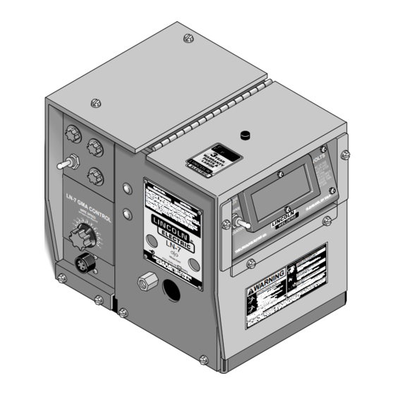
LN-7 GMA Wire Feeder
For use with machines having Code Numbers:
LN-7 GMA shown with option-
al K417 digital meter kit and
K418 GMA timer kit.
SERVICE MANUAL
Sales and Service through Subsidiaries and Distributors Worldwide
9168
9386
9643
9796
9928
9931
S E
R I
T h
A L
is
fo ll
m a
N O
o w
c h
4 ,2
L N
in g
in e
.
4 7
7 ,8
p a
a n
,7 5
te n
0 3
d th
- 7
E u
,4 2
1 ;
ts :
A u
e a
ro p
1 ;
U n
N e
s tr
c c
e a
P I
a li
it e
e s
G M
th e
1 ,1
n P
7 ,9
a 4
d s
s o
rl a
0 5
ri e
0 2
n d
a te
6 7
ta te
K in
,5 0
,4 4
s a
C O
,5 0
s ,
n t
s 3
A C
O th
g d
2 ;
It a
8 5
9 ;
7 ;
re
o m
,8 0
c o
M e
ly ,
2 7
C a
4 9
e r
S w
n a
9 ,5
6 ,6
v e
p a
1 ,5
x ic
(F ra
re d
e d
d a
0 2
9 5
te n
2 9
o 1
n c
; 3
b y
W I
O N
,7 2
e n
9 6
; 5
ts
4 7
); F
e ,
5 ,4
1 7
.9 7
o n
p e
6 ;
,0 1
W
R E
8 7
,1 2
5 ,6
e o
n d
1 ,5
9 ;
ra n
e s
IN
in g
t G
; 1
0 ;
1 6
C H
T R
7 9
S .
c e
,0 4
5 2
S P
.
,7 0
K o
7 3
e rm
1 ,1
5 ,5
E S
0 ;
re a
.0 1
a n
E E
8 1
P E
W .
1 9
4 7
y ,
O L
7 ;
U n
D
G e
0 6
3 5
R
rm
7 5
it e
3 0
M IN
4 ;
0
0
a n
S w
3 4
4 0
2 5
U T
y 2
e d
0
0
E
5 5
e n
0 2
2 0
4 5
0
0
1 5
5 0
0
0
5 5
1 0
0
0
6 0
0
L N
6 5
0
- 7
7 0
0
N E
1 1
M A
5 V
, 5
E W
0 / 6
3
0 H
Z
A M
Premier Manufacturer of Industrial Motors
SVM 106-A
February, 1995
D E
N O
.
r m
; 4
o re
,2 4
o f
4 1
6 ,4
; B
th e
; 1
6 3
,0 9
ra z
;
d K
3 ,1
il 7
5 9
9 ,7
4 7
in g
7 ;
d o
; 1
8 7
,1 1
; P
7 8
m ,
7 8
9 ,6
I
7 8
0 5
1 4
7 5
7 4
; 2
1 1
8 2
2 -5
7 l
;
It a
3 2
; U
ly
9 3
n it
e d
.
N IN
A R
W
M E
IS
T H
F U
n g
A D
R E
d a
p yo
K ee
en
U se
ep
ke
ra
P S
to
ne
ge
G
E L
W
e o
fi r
I N
t w
no
D o
t w
no
R N
D o
er
m at
C
A R
l
r n
k il
ith
W A
d e
w
b u
n
c a
ro
r ey
e le
ct
ea
K
o rk
W
U D
O C
o r
d .
o r
w
a rt
s
u n
S O
S H
l p
d e
s
L A
R A
g ro
g lo
ve
P E
L A
ri ca
d
in
si
T:
L' O
E R
IC
ct
a n
s.
g ,
o r
e r.
E N
T R
e le
o rk
g lo
ve
in
e r
e ld
E M
R
LT
e
g
w
o th
n d
P U
S U
E C
liv
in
g
u r
cl
, u
) w
T IS
E S
O N
E L
o th
fr o
m
tin
o n
ir e
E R
S R
s h
u ch
cl
e lf
la
yo
(w
A V
. C
b li
t to
e t
in
su
e r
if
in
g
g e
E S
A IL
p u
n o
o r
w
u rs
ry
o rk
B L
A V
C F
o
yo
r d
e ld
t:
lta
o l.
",
D
in
te
e a
w
if
w
e n
t vo
n tr
T R
in g
2 9
sk
la
w
A C
o r
m
a n
IS
N S
,
s ,
G
su
p
u ip
n st
co
T H
u tt
In
a ys
t u
se
m
e q
e r
g e
d
g .
E
IO
T S
d C
a rd
N IN
A lw
n o
d a
.
g
co
lta
o ve
in
IC
C T
E E
is
ce
in
D
C
e ld
vo
ic
R V
R U
S H
a n
n d
A R
D
o
a
p la
w
w
d
re
m
rv
S E
S T
S ta
a re
o rk
fo
llo
a tic
k)
ce
ls
se
T A
in g
W
e
m
tic
d u
n e
re
O F
IN
D A
th
IS
w
th
u to
l (s
re
p a
b e
fo
S E
E 'S
Y
e ld
e a
T H
se
ia
u a
ith
e r
, U
U R
E T
U
S e
m
a n
w
ith
A F
W
d H
V E
M
e r
w
o w
L L
C T
a n
C
e ld
te
t p
S TA
F A
L S
in
M O
D
w
p e
ra
p u
N U
R IA
ty
fe ty
A c
t o
in
IN
M A
a fe
R E
n o
e ct
L D
T E
S a
n n
O U
E
M A
"S
T
D
o
S H
T H
D
H A
N O
is
co
O W
A N
4 9
.1
D
A L
O S
O N
L L
E S
Z
O
R S
F O
T IC
6 ;
. D
A C
a rd
1 2
P E
A N
D
S .
n d
3 3
0 2
D
P R
L E
0 4
IE
A D
T Y
ta
d a
. 2
IF
R E
F E
A B
l S
lo ri
A L
U M
Q U
N T.
S A
N S
n a
i, F
D .C
M E
'S
ti o
n ,
LY
E R
C O
N a
ia m
O N
U IP
O Y
R
g to
E Q
F O
a n
., M
P L
S )
h in
E M
ri c
R d
a s
S D
m e
(M
n e
, W
e A
e u
e J
ic e
S e
O ff
0 L
n g
5 5
n ti
P ri
R S
.
H E
O T
&
L F
S E
U R
b e
Y O
n
T
c a
E C
h
O T
S
a lt
S E
h e
P R
G A
th ,
d
G ,
u r
e an
bo
D
y o
or
g w
on
A N
ar
c,
s to
th e
th in
S
.
ea
o u
es
t at
br
e
e r
fu m
us
ur
u s
ha
yo
c a
t of
n or
ex
m
ou
s fro
n
ad
tio
se
c a
he
nt ila
d ga
ur
ve
K S
gh
an
le
ou
fu m
es
A R
ab
.
m m
l ar
ea
S P
n .
fla
ia l.
ld
G
s io
er
he
d
m at
ve
a n
D IN
x p
lo
ha
e s
ab
le
ch
r e
m m
w hi
e y
rs
ar
fla
ne
r e
D E
D E
ne
nt ai
E S
el d
co
ju
N E
on
in
Q U
Z O
N .
el d
n
R IS
c a
L A
IO
ia l
D E
S
A T
Y S
N IS
IL IS
ty ,
tio
n
T E
D A
R A
.
ot ec
O R
U T
c ie
N E
S
T
S o
n t
s k
in
pr
M P
O N
A N
m e
dy
C O
A V
in g
d bo
R S
U E
e rn
9 6
r an
R C
P E
e ld
o v
6 1
e ea
L' A
N IQ
L E
C H
S
W
. G
M 1
E
A
a n
U R
O U
T E
U .S
V M
U R
E
ri c
T IC
m e
m
T E
N O
fr o
e A
b le
th
b y
a ila
A v
e d
1 0
1 9
R
Advertisement
Chapters
Table of Contents
Troubleshooting

Related Manuals for Lincoln Electric SVM 106-A


Summary of Contents for Lincoln Electric SVM 106-A
- Page 1 1 ,1 K in ,5 0 O th M IN al K417 digital meter kit and K418 GMA timer kit. SVM 106-A February, 1995 in e te n d th ts : s tr a li it e...
- Page 2 Miami, Florida 33135 or CSA Standard W117.2-1974. A Free copy of “Arc Welding Safety” booklet E205 is available from the Lincoln Electric Company, 22801 St. Clair Avenue, Cleveland, Ohio 44117-1199. BE SURE THAT ALL INSTALLATION, OPERATION, MAINTENANCE AND REPAIR PROCEDURES ARE PER- FORMED ONLY BY QUALIFIED INDIVIDUALS.
- Page 3 WELDING SPARKS can cause fire or explosion. 4.a. Remove fire hazards from the welding area. If this is not possible, cover them to prevent the welding sparks from starting a fire. Remember that welding sparks and hot materials from welding or cutting can easily go through small cracks and openings to adjacent areas.
-
Page 4: Safety
FOR ENGINE powered equipment. 7.a. Turn the engine off before troubleshooting and maintenance work unless the maintenance work requires it to be running. ____________________________________________________ 7.b. Operate engines in open, well-ventilated areas or vent the engine exhaust fumes outdoors. ____________________________________________________ 7.c. Do not add the fuel near an open flame welding or cutting arc or when the engine is running. - Page 5 PRÉCAUTIONS DE SÛRETÉ Pour votre propre protection lire et observer toutes les instructions et les précautions de sûreté specifiques qui parraissent dans ce manuel aussi bien que les précautions de sûreté générales suiv- antes: Sûreté Pour Soudage A L’Arc 1. Protegez-vous contre la secousse électrique: a.
-
Page 6: Table Of Contents
MASTER TABLE OF CONTENTS FOR ALL SECTIONS Safety ........... . Installation . - Page 7 TABLE OF CONTENTS - INSTALLATION SECTION - Installation ..........Section A Technical Specifications .
-
Page 8: Installation
TECHNICAL SPECIFICATIONS – LN-7 GMA Supplied by power source: 115 VAC, 50/60 Hz, 2.5 Amps 75 in. to 700 in. per minute (1.90 to 17.8 m/min) 0.023 in. through 1/16 in. (0.6 through 1.6 mm) 0.045 in. through 5/64 in. (1.2 through 2.0 mm) WITHOUT WIRE STAND... -
Page 9: Mounting Location
Control - Connection Diagram LN-7 GMA To CV/CVI Power Source (K867/K775) - Connection Diagram LN-7 GMA To R3S-250 or R3S-325 - Connection Diagram LN-7 GMA To SAM Motor Generator or Engine Welder - Connection Diagram A.10 LN-7 GMA To DC-600 - Connection Diagram A.11... - Page 10 1. For K291 and K404 cables, connect the end of the control cable with the lugged leads to the power source. If lead #21 is extended to work, do not connect leads to terminal #21 on terminal strip. Include any jumpers called for on the connection diagram.
- Page 11 5. Connect the input control cable polarized Amphenol plug into the mating 6-pin receptacle on the rear of the control section. 6. Referring to Figure A.2, install the input cable under the wire reel mounting stand strain relief FIGURE A.2 – STRAIN RELIEF CLAMP. INSTALLATION clamp.
- Page 12 FIGURE A.3 – LN-7 GMA TO DC-400, DC-250 AND CV/CVI POWER SOURCES WITH TERMINAL STRIP - CONNECTION DIAGRAM. – LN-7 GMA WIRE FEEDER INSTALLATION TURN INPUT POWER OFF WARNING BEFORE CONNECTING THE LN-7 GMA WIRE FEEDER. ELECTRIC SHOCK CAN KILL CLEVELAND, OHIO U.S.A...
- Page 13 INSTALLATION FIGURE A.4 – LN-7 GMA TO PULSED POWER 500 - CONNECTION DIAGRAM. TURN INPUT POWER OFF WARNING BEFORE CONNECTING THE LN-7 GMA WIRE FEEDER. ELECTRIC SHOCK CAN KILL – CLEVELAND, OHIO U.S.A LN-7 GMA WIRE FEEDER...
- Page 14 INSTALLATION FIGURE A.5 – LN-7 GMA TO CV/CVI POWER SOURCES WITH 14 PIN AMPHENOL CONNECTOR - CONNECTION DIAGRAM. TURN INPUT POWER OFF WARNING BEFORE CONNECTING THE LN-7 GMA WIRE FEEDER. ELECTRIC SHOCK CAN KILL – CLEVELAND, OHIO U.S.A LN-7 GMA WIRE FEEDER...
- Page 15 INSTALLATION FIGURE A.6 – LN-7 GMA TO CV/CVI POWER SOURCES WITH TWIST-MATE CONNECTOR AND 14 PIN AMPHENOL/REMOTE CONTROL - CONNECTION DIAGRAM. WARNING ELECTRIC SHOCK CAN KILL – TURN OFF INPUT POWER TO THE WELDING POWER SOURCE USING THE DISCONNECT SWITCH AT THE FUSE BOX BEFORE CONNECTING THE WIRE FEEDER.
- Page 16 A-10 FIGURE A.7 – LN-7 GMA TO CV/CVI POWER SOURCE (K867/K775) - CONNECTION DIAGRAM. – LN-7 GMA WIRE FEEDER INSTALLATION TURN INPUT POWER OFF WARNING BEFORE CONNECTING THE LN-7 GMA WIRE FEEDER. ELECTRIC SHOCK CAN KILL CLEVELAND, OHIO U.S.A...
- Page 17 INSTALLATION FIGURE A.8 – LN-7 GMA TO R3S-250 OR R3S-325 - CONNECTION DIAGRAM. TURN INPUT POWER OFF WARNING BEFORE CONNECTING THE LN-7 GMA WIRE FEEDER. ELECTRIC SHOCK CAN KILL – CLEVELAND, OHIO U.S.A LN-7 GMA WIRE FEEDER A-11...
- Page 18 A-12 FIGURE A.9 – LN-7 GMA TO SAM MOTOR GENERATOR OR ENGINE WELDER - CONNECTION DIAGRAM. LN-7 GMA WIRE FEEDER INSTALLATION TURN INPUT POWER OFF WARNING BEFORE CONNECTING THE LN-7 GMA WIRE FEEDER. ELECTRIC SHOCK CAN KILL CLEVELAND, OHIO U.S.A...
- Page 19 INSTALLATION A-13 FIGURE A.10 – LN-7 GMA TO DC-600 - CONNECTION DIAGRAM. TURN INPUT POWER OFF WARNING BEFORE CONNECTING THE LN-7 GMA WIRE FEEDER. ELECTRIC SHOCK CAN KILL – CLEVELAND, OHIO U.S.A LN-7 GMA WIRE FEEDER...
- Page 20 A-14 FIGURE A.11 – LN-7 GMA TO R3S-400, 600, OR 800 - CONNECTION DIAGRAM. LN-7 GMA WIRE FEEDER INSTALLATION TURN INPUT POWER OFF WARNING BEFORE CONNECTING THE LN-7 GMA WIRE FEEDER. ELECTRIC SHOCK CAN KILL CLEVELAND, OHIO U.S.A...
- Page 21 FIGURE A.12 – LN-7 GMA TO MOST LINCOLN MOTOR GENERATORS - CONNECTION DIAGRAM. WARNING ELECTRIC SHOCK CAN KILL INSTALLATION TURN INPUT POWER OFF BEFORE CONNECTING THE LN-7 GMA WIRE FEEDER. CLEVELAND, OHIO U.S.A A-15 LN-7 GMA WIRE FEEDER...
- Page 22 THE LN-7 GMA CONTROL CIRCUIT WILL BE DAMAGED. THE ENGINE GOVERNOR SETTING IS PRE-SET AT THE AUXILIARY FACTORY - DO NOT ADJUST VOLTAGE MUST ABOVE RPM SPECIFICATIONS NOT EXCEED LISTED IN ENGINE WELDER 140 VOLTS. OPERATING MANUAL. CLEVELAND, OHIO U.S.A...
- Page 23 INSTALLATION FIGURE A.14 – LN-7 GMA TO RANGER 9 – CONNECTION DIAGRAM. WARNING DO NOT OPERATE WITH PANELS OPEN. DISCONNECT NEGATIVE (-) BATTERY LEAD BEFORE SERVICING. ELECTRIC DO NOT TOUCH SHOCK ELECTRICALLY LIVE PARTS. CAN KILL WARNING KEEP GUARDS IN PLACE. KEEP AWAY FROM MOVING PARTS.
- Page 24 A-18 FIGURE A.15 – LN-7 GMA TO RANGER 10-LX – CONNECTION DIAGRAM. WARNING DO NOT OPERATE WITH PANELS OPEN. DISCONNECT NEGATIVE (-) BATTERY LEAD BEFORE SERVICING. ELECTRIC DO NOT TOUCH SHOCK ELECTRICALLY LIVE PARTS. CAN KILL LN-7 GMA WIRE FEEDER INSTALLATION WARNING KEEP GUARDS IN PLACE.
- Page 25 FIGURE A.16 – LN-7 GMA TO POWER SOURCES WITH NO OUTPUT CONTACTOR - CONNECTION DIAGRAM. TURN INPUT POWER OFF WARNING BEFORE CONNECTING THE LN-7 GMA WIRE FEEDER. ELECTRIC SHOCK CAN KILL INSTALLATION CLEVELAND, OHIO U.S.A A-19 LN-7 GMA WIRE FEEDER...
- Page 26 A-20 FIGURE A.17 – LN-7 GMA TO POWER SOURCES WITH CONTACTOR AND NO TERMINAL LN-7 GMA WIRE FEEDER INSTALLATION STRIP - CONNECTION DIAGRAM. TURN INPUT POWER OFF WARNING BEFORE CONNECTING THE LN-7 GMA WIRE FEEDER. ELECTRIC SHOCK CAN KILL CLEVELAND, OHIO U.S.A...
-
Page 27: Work Cable
WORK CABLE Connect a work lead of sufficient size and length (Table A.2) between the proper output stud on the power source and the work. Be sure the connection to the work makes tight metal-to-metal electrical contact. Poor work lead connections can result in the grounding lead protector being activated. -
Page 28: Water Connections (For Water Cooled Guns
A-22 WATER CONNECTIONS (FOR WATER COOLED GUNS) The LN-7 GMA must have a K527 Water Solenoid Kit installed (see the Accessories Section). The K440-1 LN-7 GMA model already has a water solenoid installed. Refer to Figure A.19 and perform the following steps: NOTE: If not using a Lincoln water cooler (such as the K877-1), and if your water cooling device is not... -
Page 29: Shielding Gas Hookup
SHIELDING GAS HOOKUP WARNING Gas under pressure is explosive. Always keep gas cylinders in an upright position and to the undercarriage or a stationary support. See American National Standard Z-49.1, “Safety In Welding And Cutting”, published by the American Welding Society. Customer must provide a cylinder of shielding gas, a pressure regulator, a flow control valve, and a hose from the flow valve to the gas inlet fitting of the LN-7... - Page 30 A-24 NOTES LN-7 GMA WIRE FEEDER...
- Page 31 TABLE OF CONTENTS - OPERATION SECTION - Operation ..........Section B Operating Instructions .
-
Page 32: Operation
OPERATING INSTRUCTIONS Read and understand the entire Operation Section prior to operating the machine. SAFETY PRECAUTIONS WARNING ELECTRIC SHOCK can kill. • Do not touch electrically live parts or electrode with skin or wet clothing. • Insulate yourself from work or ground. -
Page 33: Controls And Settings
CONTROLS AND SETTINGS Operator controls are illustrated in Figure B.1. Refer to the figure and the following explanations of the controls. WIRE FEED SPEED CONTROL. This control sets the feed speed of the wire feeder. Turn the knob to the left for slower speeds and to the right for higher speeds. -
Page 34: Circuit Protection
CIRCUIT PROTECTION A manual reset circuit breaker protects the AC supply line and the wire feeder from overloads, usually caused by excessive wire drag or other wire feed problems. To reset the circuit breaker, raise the cover of the wire drive compartment and push the white button on the side of the control box above the drive rolls. - Page 35 OPERATION FIGURE B.2 – INSTALLING DRIVE ROLLS ON A TWO-ROLL FEEDER. LN-7 GMA WIRE FEEDER...
-
Page 36: Changing Drive Rolls For Four-Roll Wire Feeders
CHANGING DRIVE ROLLS FOR FOUR- ROLL WIRE FEEDERS: To change drive rolls on a four-roll wire feeder, refer to Figure B.3 and perform the following steps: 1. Remove the gun and cable from the conductor block on the feeder by loosening the hand screw and pulling the gun straight out of the block. - Page 37 FIGURE B.3 – INSTALLING DRIVE ROLLS ON A FOUR-ROLL FEEDER. DRIVE ROLL HALVES GUIDE TUBE DETAIL OUTGOING GUIDE TUBE OUTGOING GUIDE TUBE INSERT OPERATION CLAMPING COLLAR SPACER (IF REQUIRED) OUTPUT SHAFT LARGE RADIUS MIDDLE GUIDE IDLE TUBE ROLL SMALL RADIUS DRIVE ROLL LN-7 GMA WIRE FEEDER...
-
Page 38: Idle Roll Pressure Setting
Two-roll wire feeders: 1. Press the end of the gun against a solid object that is electrically isolated from the welder output and press the trigger for several seconds. 2. If the wire “birdnests”, jams, or breaks at the drive roll, the idle roll pressure is set too high. -
Page 39: Wire Loading
WIRE LOADING WIRE REEL LOADING – READI-REELS AND SPOOLS TO MOUNT A 30 LB READI-REEL PACKAGE USING THE MOLDED PLASTIC K363-P TYPE ADAPTER: 1. Make certain that the threaded locking collar is tight and securely locks the adapter on the spindle. - Page 40 B-10 TO MOUNT 10 TO 30 LB SPOOL (12” DIAMETER): (For 8 in. spools a K468 spindle adapter must be used.) 1. Remove the locking collar and Read-Reel adapter shipped on the 2 in. diameter spindle (adapter is not required). 2.
-
Page 41: Wire Reel Loading - 50 And 60 Lb Coils
WIRE REEL LOADING – 50 AND 60 LB COILS (K303 OR K376 WIRE REEL STAND) ADJUSTABLE WIRE REEL BRAKE The mount for standard 50 and 60 pound electrode coils includes a two-position brake assembly. Generally the brake should be at the inner position (nearest to the wire reel shaft) for wire feed speeds below 400 in./min (10 m/min). -
Page 42: Wire Loading - 13-14 Lb Innershield Coils
B-12 FEEDING ELECTRODE 1. Turn the reel until the free end of the electrode is accessible. 2. While tightly holding the electrode, cut off the bent end and straighten the first six inches. Cut off the first inch. (If the electrode is not properly straightened, it may not feed or may not go into the outgoing guide tube causing a “birdnest”.) 3. -
Page 43: Acceleration Setting
ACCELERATION SETTING The LN-7 GMA can be configured for optimum starting for different procedures by selecting between two speeds of controlled wire acceleration. As shipped from the factory, the LN-7 GMA models are set for fast acceleration. Fast acceleration is typically the best for most smaller wire procedures. -
Page 44: Making A Weld
B-14 MAKING A WELD 1. Inch the electrode through the gun and cable. For solid wire, cut the electrode within approximately 3/8 in. of the end of the contact tip. If using cored wire, cut the electrode within 3/4 in. of the extension guide. -
Page 45: Flux Tank Loading
FLUX TANK LOADING K320 FLUX TANK (OPTIONAL) Either turn off the incoming air line or remove the quick disconnect if one has been installed. Slightly loosen the tank cap and let the air in the tank escape in the holes in the side of the cap. - Page 46 B-16 NOTES LN-7 GMA WIRE FEEDER...
- Page 47 TABLE OF CONTENTS - ACCESSORIES SECTION - Accessories ..........Section C General .
-
Page 48: Accessories
GENERAL The following is a list of the accessories that can be used with the LN-7 GMA wire feeder. Product Number K178-1 K162H K163 K419 K418 K416 K417 K775/K857 K320 K376/K303 S-14543 M-11514 K377 K378 K292 K291 K404 K480 K126 K115 K112 K113... -
Page 49: Auxiliary Equipment Connection
ACCESSORIES AUXILIARY EQUIPMENT CONNECTION The LN-7 GMA has the factory installed gas solenoid valve leads attached to terminals 7 and 32A. Additional auxiliary equipment connection is not recommended. If the gas solenoid is NOT connected to terminals 7 and 32A, other auxiliary equipment may be connected but the current draw must NOT exceed 1/4 ampere. -
Page 50: K418 Gma Timer Kit
K418 GMA TIMER KIT This kit is available to provide the following functions: 1. Preflow Control – Provides flow of shielding gas to the work before the arc is established. The solenoid valve is energized immediately when the gun trigger is closed, but the time delay before the wire feeder is energized is adjustable to between 0 and 1.5 seconds. -
Page 51: Wire Reel Dust Shield For K376 50 To 60 Lb Wire Reel Mounting Stand
ACCESSORIES WIRE REEL DUST SHIELD FOR K376 50 TO 60 LB WIRE REEL MOUNTING STAND A shield is available to cover the wire and reel to protect the wire from falling dirt and dust. Order part no. S-14543. Instructions are provided with the kit. WIRE REEL DUST SHIELD DOOR FOR K303 AND K376 In extremely dusty and dirty locations this... -
Page 52: K480 Input Cable
K480 INPUT CABLE The K480 input cable includes a 2/0 (67 mm ) weld cable with a Twist-Mate connector and a 14-pin (MS-3106A-20- 27PX) plug to be compatible with the smaller Lincoln power sources (such as the CV-300). The K480 is rated at 400 amps, 60% duty cycle and is available in 10, 25, and 50 foot (3.0, 7.6, and 15.2 m) lengths. -
Page 53: Attaching The Wire Reel Stand
ACCESSORIES SUBMERGED ARC GUNS The K112 gun and cable assembly is recommended for welding with 1/16 in. solid steel electrode at up to 500 amps. The K113 gun and cable is recommended for 5/64 in. and 3/32 in. (2.0 and 2.4 mm) solid steel electrodes (types L50, L60, L61, and L70) for use up to 600 amps. - Page 54 NOTES LN-7 GMA WIRE FEEDER...
-
Page 55: Maintenance . . . . . . . . . . . . . . . . . . . . . . . . . . . . . . . . . . . . . . . . . . . . . . . Section D Routine Maintenance
TABLE OF CONTENTS - MAINTENANCE SECTION - Maintenance ..........Section D Routine Maintenance . -
Page 56: Maintenance
ROUTINE MAINTENANCE DRIVE ROLLS AND GUIDE TUBES After feeding every coil of wire, inspect the drive roll section. Clean the assembly as necessary. Do not use solvent to clean the drive roll assembly as it may wash the lubricant out of the bearings. The drive rolls and guide tubes are stamped with the wire sizes they will feed. -
Page 57: Protective Circuits
TABLE OF CONTENTS - THEORY OF OPERATION SECTION - Theory of Operation ......... Section E General . -
Page 58: Theory Of Operation
GENERAL The LN-7 GMA wire feeder is available in two versions, a two-roll and a four-roll wire FIGURE E.1 – INPUT LINE VOLTAGE AND TRIGGER TRANSFORMER. 8.8 VAC CIRCUIT TRIGGER BREAKER TRANS- FORMER FROM 24 VAC 115 VAC WELDING POWER SUPPLY CONTROL CIRCUIT OPERATION... -
Page 59: Trigger Circuit
THEORY OF OPERATION 8.8 VAC CIRCUIT TRIGGER BREAKER TRANS- FORMER FROM 24 VAC 115 VAC WELDING POWER SUPPLY TRIGGER CIRCUIT The 24 VAC output of the trigger transformer is sent to the control PC board and rectified by a diode network. When the gun trigger is NOTE: Unshaded areas of block logic diagrams are the subject of discussion. -
Page 60: Control Relay Circuit
8.8 VAC CIRCUIT TRIGGER BREAKER TRANS- FORMER FROM 24 VAC 115 VAC WELDING POWER SUPPLY CONTROL RELAY CIRCUIT The first contact closes to allow 115 VAC to energize the gas solenoid. This allows shielding gas to flow to the gun. The second contact of the control relay closes the circuit in the welding power source contactor circuit. -
Page 61: Auxiliary Circuits
THEORY OF OPERATION 8.8 VAC CIRCUIT TRIGGER BREAKER TRANS- FORMER FROM 24 VAC 115 VAC WELDING POWER SUPPLY AUXILIARY CIRCUITS TIMER KITS The optional GMA Timer and Burnback kits can be added to provide time delays for these functions. Both kits provide a burnback control which maintains the welding power source contacts closed for a short time after the trigger is released. -
Page 62: Protective Circuits
8.8 VAC CIRCUIT TRIGGER BREAKER TRANS- FORMER FROM 24 VAC 115 VAC WELDING POWER SUPPLY PROTECTIVE CIRCUITS Protective circuits are designed in to the LN-7 GMA to detect trouble and shut down the wire feeder before any damage to the feeder can result. -
Page 63: Scr Operation
THEORY OF OPERATION GROUND LEAD PROTECTION The Ground Lead Protector (GLP) circuit protects the ground lead that connects the wire feeder to the welding power source. When the circuit detects any current flow in the ground lead, a contact closes in the control circuit which de-energizes the control relay. - Page 64 NOTES LN-7 GMA WIRE FEEDER...
-
Page 65: Troubleshooting And Repair . . . . . . . . . . . . . . . . . . . . . . . . . . . . . . . . . . Section F How To Use Troubleshooting Guide
TABLE OF CONTENTS - TROUBLESHOOTING AND REPAIR SECTION - Troubleshooting And Repair ........Section F How To Use Troubleshooting Guide . - Page 66 TROUBLESHOOTING AND REPAIR How To Use Troubleshooting Guide Service and Repair should only be performed by Lincoln Electric Factory Trained Personnel. Unauthorized repairs performed on this equipment may result in danger to the technician and machine operator and will invalidate your factory warranty. For your safety and to avoid Electrical Shock, please observe all safety notes and precautions detailed throughout this manual.
-
Page 67: Troubleshooting And Repair
TROUBLESHOOTING AND REPAIR PC BOARD TROUBLESHOOTING PROCEDURES fuse box before working on equipment. Do not touch electrically hot parts. Sometimes machine failures appear to be due to PC board failures. These problems can sometimes be traced to poor electrical connections. To avoid problems when trou- bleshooting and replacing PC boards, please use the following procedure: 1. -
Page 68: Troubleshooting Guide
Electric Service Department for technical troubleshooting assistance before you proceed. Call 216-383-2531 or 1-800-833-9353. LN-7 GMA WIRE FEEDER POSSIBLE AREAS OF MISADJUSTMENT(S) FUNCTIONAL PROBLEMS Contact Lincoln Electric Service Department (216-383-2531) or 1-800-833-9353 (WELD). 1. Make sure power source is on and supplying 115 VAC to the wire feeder. -
Page 69: Troubleshooting Guide
TROUBLESHOOTING AND REPAIR Troubleshooting Guide – See Wiring Diagrams for location of specified components. See Wiring Diagrams for troubleshooting of specific circuits. PROBLEMS (SYMPTOMS) FUNCTIONAL PROBLEMS (Continued) When the gun trigger is pulled there is no wire feed, but gas flows and arc voltage is present. - Page 70 TROUBLESHOOTING AND REPAIR Troubleshooting Guide – See Wiring Diagrams for location of specified components. See Wiring Diagrams for troubleshooting of specific circuits. PROBLEMS (SYMPTOMS) FUNCTIONAL PROBLEMS (Continued) When the gun trigger is pulled the wire feeds, the gas flows, but there is NO arc voltage.
- Page 71 TROUBLESHOOTING AND REPAIR Troubleshooting Guide – See Wiring Diagrams for location of specified components. See Wiring Diagrams for troubleshooting of specific circuits. PROBLEMS (SYMPTOMS) FUNCTIONAL PROBLEMS (Continued) When the gun trigger is pulled there IS wire feed and arc voltage but there is NOT any gas flow.
- Page 72 TROUBLESHOOTING AND REPAIR Troubleshooting Guide – See Wiring Diagrams for location of specified components. See Wiring Diagrams for troubleshooting of specific circuits. PROBLEMS (SYMPTOMS) FUNCTIONAL PROBLEMS (Continued) Wire feed speed adjustment is rough. Works only at certain portions of the speed range. Ground Lead Protector circuit tripping.
- Page 73 TROUBLESHOOTING AND REPAIR Troubleshooting Guide – See Wiring Diagrams for location of specified components. See Wiring Diagrams for troubleshooting of specific circuits. PROBLEMS (SYMPTOMS) FUNCTIONAL PROBLEMS (Continued) Wire feeder circuit breaker tripping when the gun trigger is pulled. If for any reason you do not understand the test procedures or are unable to perform the tests/repairs safely, contact the Lincoln Electric Service Department for technical troubleshooting assistance before you proceed.
-
Page 74: Test Procedures
2. Check idle roll pressure, brake tension, drive roll cleanliness. drive roll tension per Operation Section - Idle Roll Pressure Setting. Possible problem with the weld procedure. Contact Lincoln Electric at 216-383-2531 or 1-800-833- 9353. The welding power source may be faulty. Check or replace. - Page 75 TROUBLESHOOTING AND REPAIR Troubleshooting Guide – See Wiring Diagrams for location of specified components. See Wiring Diagrams for troubleshooting of specific circuits. PROBLEMS (SYMPTOMS) WIRE FEEDING AND WELDING PROBLEMS (Continued) The wire feeds but starts and stops intermittently. If for any reason you do not understand the test procedures or are unable to perform the tests/repairs safely, contact the Lincoln Electric Service Department for technical troubleshooting assistance before you proceed.
-
Page 76: Test Procedures
F-12 TROUBLESHOOTING AND REPAIR TEST PROCEDURES Service and repair should only be performed by Lincoln Electric factory trained personnel. Unauthorized repairs performed on this equipment may result in danger to the technician or machine operator and will invalidate your factory warranty. - Page 77 TROUBLESHOOTING AND REPAIR CONTROL RELAY TEST (continued) FIGURE F.1 – CONTROL RELAY TEST POINTS. – 24 VDC TEST PROCEDURE 1. Remove the control relay from the control box per the Control Relay Replacement procedure. 2. Connect a 24 VDC supply to terminals A and B on the control relay.
-
Page 78: Trigger Transformer Test
TROUBLESHOOTING AND REPAIR TRIGGER TRANSFORMER TEST Service and repair should only be performed by Lincoln Electric factory trained personnel. Unauthorized repairs performed on this equipment may result in danger to the technician or machine operator and will invalidate your factory warranty. - Page 79 TROUBLESHOOTING AND REPAIR TRIGGER TRANSFORMER TEST (continued) FIGURE F.2 – TRIGGER TRANSFORMER TEST POINTS. 8.8 VAC 24 VAC TEST PROCEDURE 1. Remove the cover from the control box by removing the four 5/16 in. screws from the top and sides of the unit. 2.
-
Page 80: Control Cable Continuity Test
TROUBLESHOOTING AND REPAIR CONTROL CABLE CONTINUITY TEST Service and repair should only be performed by Lincoln Electric factory trained personnel. Unauthorized repairs performed on this equipment may result in danger to the technician or machine operator and will invalidate your factory warranty. - Page 81 TROUBLESHOOTING AND REPAIR CONTROL CABLE CONTINUITY TEST (continued) FIGURE F.3 – CONTROL CABLE CONTINUITY TEST POINTS. CONTROL CABLE AMPHENOL PLUG TEST PROCEDURE 1. Disconnect the control cable amphenol plug from the welding power source and the wire feeder. 2. Using a multimeter, measure the resistance of the control cable wiring from the amphenol plug on the wire feeder end to the terminal connectors...
-
Page 82: Component Replacement Procedures
F-18 TROUBLESHOOTING AND REPAIR COMPONENT REPLACEMENT PROCEDURES WIRE FEED SPEED POTENTIOMETER REPLACEMENT ELECTRIC SHOCK can kill. • Observe all safety precautions detailed throughout this manual. Turn off input power to the wire feeder. Only qualified technicians should perform installations, maintenance, and troubleshooting work on the machine. - Page 83 TROUBLESHOOTING AND REPAIR WIRE FEED SPEED POTENTIOMETER REPLACEMENT (continued) FIGURE F.4 – REMOVING WIRE FEED SPEED POTENTIOMETER. POTENTIOMETER CONTROL BOX COVER 5/16 IN. SCREW REPAIR PROCEDURE 1. Remove the cover from the control box by removing the four 5/16 in. screws from the top and side of the unit.
- Page 84 F-20 TROUBLESHOOTING AND REPAIR WIRE FEED SPEED POTENTIOMETER REPLACEMENT (continued) 6. Place the new potentiometer through the case from the inside. Ensure that the index pin on the potentiometer fits in the locating hole on the case of the wire feeder.
-
Page 85: Circuit Breaker Replacement
TROUBLESHOOTING AND REPAIR CIRCUIT BREAKER REPLACEMENT ELECTRIC SHOCK can kill. • Observe all safety precautions detailed throughout this manual. Turn off input power to the wire feeder. Only qualified technicians should perform installations, maintenance, and troubleshooting work on the machine. TOOLS REQUIRED 5/16 in. - Page 86 F-22 TROUBLESHOOTING AND REPAIR CIRCUIT BREAKER REPLACEMENT (continued) FIGURE F.5 – CIRCUIT BREAKER AND PUSH BUTTON REPLACEMENT. CIRCUIT BREAKER PUSH BUTTON REPAIR PROCEDURE 1. Remove the cover from the control box by removing the four 5/16 in. screws from the top and side of the unit. 2.
-
Page 87: Ground Lead Protector Push Button Switch Replacement
TROUBLESHOOTING AND REPAIR GROUND LEAD PROTECTOR PUSH BUTTON SWITCH REPLACEMENT ELECTRIC SHOCK can kill. • Observe all safety precautions detailed throughout this manual. Turn off input power to the wire feeder. Only qualified technicians should perform installations, maintenance, and troubleshooting work on the machine. - Page 88 F-24 TROUBLESHOOTING AND REPAIR GROUND LEAD PROTECTOR PUSH BUTTON SWITCH REPLACEMENT (continued) REPAIR PROCEDURE 1. Remove the cover from the control box by removing the four 5/16 in. screws from the top and side of the unit. 2. Remove the retaining nut from the front of the push button and remove the push button from the control box.
-
Page 89: Trigger Transformer Replacement
TROUBLESHOOTING AND REPAIR TRIGGER TRANSFORMER REPLACEMENT ELECTRIC SHOCK can kill. • Observe all safety precautions detailed throughout this manual. Turn off input power to the wire feeder. Only qualified technicians should perform installations, maintenance, and troubleshooting work on the machine. TOOLS REQUIRED 5/16 in. - Page 90 F-26 TROUBLESHOOTING AND REPAIR TRIGGER TRANSFORMER REPLACEMENT (continued) FIGURE F.6 – TRIGGER TRANSFORMER REPLACEMENT. TRIGGER TRANSFORMER REPAIR PROCEDURE 1. Remove the cover from the control box by removing the four 5/16 in. screws from the top and side of the unit. 2.
-
Page 91: Ground Lead Protector Reed Switch Replacement
TROUBLESHOOTING AND REPAIR GROUND LEAD PROTECTOR REED SWITCH REPLACEMENT ELECTRIC SHOCK can kill. • Observe all safety precautions detailed throughout this manual. Turn off input power to the wire feeder. Only qualified technicians should perform installations, maintenance, and troubleshooting work on the machine. TOOLS REQUIRED 5/16 in. - Page 92 F-28 TROUBLESHOOTING AND REPAIR GROUND LEAD PROTECTOR REED SWITCH REPLACEMENT (continued) FIGURE F.7 – REED SWITCH REPLACEMENT. REED SWITCH WRAPS PART OF MAIN WIRE HARNESS REPAIR PROCEDURE 1. Remove the cover from the control box by removing the four 5/16 in. screws from the top and side of the unit.
-
Page 93: Control Pc Board Replacement
TROUBLESHOOTING AND REPAIR CONTROL PC BOARD REPLACEMENT ELECTRIC SHOCK can kill. • Observe all safety precautions detailed throughout this manual. Turn off input power to the wire feeder. Only qualified technicians should perform installations, maintenance, and troubleshooting work on the machine. TOOLS REQUIRED 5/16 in. - Page 94 F-30 TROUBLESHOOTING AND REPAIR CONTROL PC BOARD REPLACEMENT (continued) FIGURE F.8 – DISCONNECTING THE CONTROL PC BOARD. LN-7 GMA CONTROL REPAIR PROCEDURE 1. Observe static precautions detailed in PC Board Troubleshooting Procedures at the beginning of this section. 2. Remove the cover from the control box by removing the four 5/16 in.
- Page 95 TROUBLESHOOTING AND REPAIR CONTROL PC BOARD REPLACEMENT (continued) FIGURE F.9 – REMOVING THE CONTROL PC BOARD. CONTROL PC BOARD 9. Pry the retaining clip from the control relay. Remove the control relay from the control PC board. 10. Disengage the PC board supports by squeezing each support in turn with a pair of pliers and gently pulling out on the board next to the support.
-
Page 96: Main Power Resistor (R 1 ) Replacement
F-32 TROUBLESHOOTING AND REPAIR MAIN POWER RESISTOR (R ELECTRIC SHOCK can kill. • Observe all safety precautions detailed throughout this manual. Turn off input power to the wire feeder. Only qualified technicians should perform installations, maintenance, and troubleshooting work on the machine. TOOLS REQUIRED 5/16 in. - Page 97 TROUBLESHOOTING AND REPAIR MAIN POWER RESISTOR (R FIGURE F.10 – MAIN POWER RESISTOR REPLACEMENT. FOR UNITS EQUIPPED WITH AN OPTIONAL METER KIT METER CABLE STRAP INSULATING SPACERS POWER RESISTOR REPAIR PROCEDURE 1. Remove the cover from the control box by removing the four 5/16 in. screws from the top and side of the wire feeder.
- Page 98 F-34 TROUBLESHOOTING AND REPAIR MAIN POWER RESISTOR (R 7. Solder the two wires onto the new power resistor. 8. Install one insulating spacer onto the resistor mounting bolt. Install the power resistor and the second spacer onto the mounting bolt. Secure in place with a flat washer and hex nut.
-
Page 99: Control Relay Replacement
TROUBLESHOOTING AND REPAIR CONTROL RELAY REPLACEMENT ELECTRIC SHOCK can kill. • Observe all safety precautions detailed throughout this manual. Turn off input power to the wire feeder. Only qualified technicians should perform installations, maintenance, and troubleshooting work on the machine. TOOLS REQUIRED 5/16 in. - Page 100 F-36 TROUBLESHOOTING AND REPAIR CONTROL RELAY REPLACEMENT (continued) FIGURE F.11 – CONTROL RELAY REPLACEMENT. CONTROL RELAY REPAIR PROCEDURE 1. Remove the cover from the control box by removing the four 5/16 in. screws from the top and side of the unit. 2.
-
Page 101: Wire Drive Assembly And Components Replacement
TROUBLESHOOTING AND REPAIR WIRE DRIVE ASSEMBLY AND COMPONENTS REPLACEMENT ELECTRIC SHOCK can kill. • Observe all safety precautions detailed throughout this manual. Turn off input power to the wire feeder. Only qualified technicians should perform installations, maintenance, and troubleshooting work on the machine. TOOLS REQUIRED 5/16 in. - Page 102 F-38 TROUBLESHOOTING AND REPAIR WIRE DRIVE ASSEMBLY AND COMPONENTS REPLACEMENT (continued) MOTOR GROUND LEAD 539(W) 541(B) REPAIR PROCEDURE 1. Remove the cover from the control by removing the four 5/16 in. screws from the top and side of the unit. 2.
- Page 103 TROUBLESHOOTING AND REPAIR WIRE DRIVE ASSEMBLY AND COMPONENTS REPLACEMENT (continued) 9. On two-roll feeders, remove the three hex head bolts, lockwashers, and flat washers from the bottom of the wire drive assembly. On four-roll feeders, remove the two straight head screws from the bottom of the wire drive assembly.
- Page 104 F-40 TROUBLESHOOTING AND REPAIR WIRE DRIVE ASSEMBLY AND COMPONENTS REPLACEMENT (continued) FIGURE F.13 – WIRE DRIVE ASSEMBLY REMOVAL (FOUR-ROLL FEEDER). PINION GEAR MOTOR INSULATOR GEARBOX MOTOR MOUNTING SCREW UPPER INSULATOR SHEET LN-7 GMA WIRE FEEDER MOTOR ROLL LOCATOR/ INSULATOR BUSHING BENT J-BOLT GEARBOX...
-
Page 105: Swing Arm Assembly Replacement For Two-Roll Wire Feeders
TROUBLESHOOTING AND REPAIR SWING ARM ASSEMBLY REPLACEMENT FOR TWO-ROLL WIRE FEEDERS ELECTRIC SHOCK can kill. • Observe all safety precautions detailed throughout this manual. Turn off input power to the wire feeder. Only qualified technicians should perform installations, maintenance, and troubleshooting work on the machine. - Page 106 F-42 TROUBLESHOOTING AND REPAIR SWING ARM ASSEMBLY REPLACEMENT FOR TWO-ROLL WIRE FEEDERS (continued) FIGURE F.14 – SWING ARM REMOVAL FOR TWO-ROLL FEEDERS. SPEED CLIP IDLE ROLL ASSEMBLY PIVOT SPACER LATCH KNOB QUICK RELEASE ASSEMBLY REPAIR PROCEDURE 1. Rotate the latch knob on the quick release assembly to the open position and swing the arm away from the gearbox.
- Page 107 TROUBLESHOOTING AND REPAIR SWING ARM ASSEMBLY REPLACEMENT FOR TWO-ROLL WIRE FEEDERS (continued) 6. Place the idle roll assembly into the groove pin. Secure in place with a speed clip. 7. Slide the pivot pin into the swing arm assembly. Place the flat washer and swing arm assembly on the gearbox F-43 assembly.
-
Page 108: Swing Arm Assembly Replacement For Four-Roll Wire Feeders
F-44 TROUBLESHOOTING AND REPAIR SWING ARM ASSEMBLY REPLACEMENT FOR FOUR-ROLL WIRE FEEDERS ELECTRIC SHOCK can kill. • Observe all safety precautions detailed throughout this manual. Turn off input power to the wire feeder. Only qualified technicians should perform installations, maintenance, and troubleshooting work on the machine. - Page 109 TROUBLESHOOTING AND REPAIR SWING ARM ASSEMBLY REPLACEMENT FOR FOUR-ROLL WIRE FEEDERS (continued) FIGURE F.15 – SWING ARM REMOVAL FOR FOUR-ROLL FEEDERS. SPACER IDLE ROLLER IDLE ROLL SHAFT PIN SPACER REPAIR PROCEDURE 1. Remove the allen head setscrew from the center post of the wire drive assembly.
- Page 110 F-46 TROUBLESHOOTING AND REPAIR SWING ARM ASSEMBLY REPLACEMENT FOR FOUR-ROLL WIRE FEEDERS (continued) 7. Place the two swing arms and spacers in the center post of the wire drive assembly. Ensure the holes in the pieces line up to accept the hinge pin. CAUTION Do not use excessive force when installing the hinge pin.
-
Page 111: Gas Solenoid And Connections Replacement
TROUBLESHOOTING AND REPAIR GAS SOLENOID AND CONNECTIONS REPLACEMENT ELECTRIC SHOCK can kill. • Observe all safety precautions detailed throughout this manual. Turn off input power to the wire feeder. Only qualified technicians should perform installations, maintenance, and troubleshooting work on the machine. TOOLS REQUIRED 5/16 in. - Page 112 F-48 TROUBLESHOOTING AND REPAIR GAS SOLENOID AND CONNECTIONS REPLACEMENT (continued) FIGURE F.16 – GAS SOLENOID DISASSEMBLY. OUTLET FITTING RETAINING TUBING SOLENOID MOUNTING PLATE TUBING TUBE SLEEVE SOLENOID OUTLET FITTING SOLENOID FILTER SCREEN INLET FITTING LN-7 GMA WIRE FEEDER...
- Page 113 TROUBLESHOOTING AND REPAIR GAS SOLENOID AND CONNECTIONS REPLACEMENT (continued) REPAIR PROCEDURE 1. Remove the cover from the control box by removing the four 5/16 in. screws from the top and side of the unit. 2. Remove the tie wraps that secure the gas solenoid wires to the wire feeder main harness.
-
Page 114: Retest After Repair
F-50 TROUBLESHOOTING AND REPAIR RETEST AFTER REPAIR If a failed test indicates that any mechanical part which could affect the machine’s electrical characteristics must be replaced, or if any electrical components are repaired or replaced, the machine must be retested and meet the following standards. Wire Feed Speed, LN-7 GMA . - Page 115 TABLE OF CONTENTS - ELECTRICAL DIAGRAMS SECTION - Electrical Diagrams ......... Section G G1706 Control PC Board Components .
- Page 116 G M A C O N T R O L D 1 1 2 NOTE: Lincoln Electric assumes no responsibility for liablilities resulting from board level troubleshooting. PC Board repairs will invalidate your factory warranty. Individual Printed Circuit Board Components are not avail- able from Lincoln Electric.
-
Page 117: Electrical Diagrams
R103,R107,R122,R124 RESISTOR-MF,1/4W,4.75K,1% NOTE: Lincoln Electric assumes no responsibility for liablilities resulting from board level troubleshooting. PC Board repairs will invalidate your factory warranty. Individual Printed Circuit Board Components are not avail- able from Lincoln Electric. This information is provided for reference only. Lincoln Electric discourages board level troubleshooting and repair since it may compromise the quality of the design and may result in danger to the Machine Operator or Technician. - Page 118 ELECTRICAL DIAGRAMS Wiring Diagram — Codes 9168 and 9386 C A S E G R O U N D I N G S T U D W I R E F E E D M O T O R 5 4 1 5 3 9 3 2 A G A S...
- Page 119 ELECTRICAL DIAGRAMS Wiring Diagram — Codes 9643 and 9796 C A S E G R O U N D I N G S T U D W I R E F E E D M O T O R 5 4 1 5 3 9 G A S S O L E N O I D ( L N - 7 G M A O N L Y )
- Page 120 ELECTRICAL DIAGRAMS Wiring Diagram — Codes 9928 and 9931 C A S E G R O U N D I N G S T U D W I R E F E E D M O T O R 5 4 1 5 3 9 G A S S O L E N O I D ( L N - 7 G M A O N L Y )
- Page 121 TO DYNAMIC BRAKING) NOTE: Lincoln Electric assumes no responsibility for liabilities resulting from board level troubleshooting. PC Board repairs will invalidate your factory warranty. This Printed Circuit Board schematic is provided for reference only. It may not be totally applic- able to your machine’s specific PC board version.