Table of Contents
Advertisement
Quick Links
RX-V861/HTR-6080/DSP-AX861SE/
This manual has been provided for the use of authorized YAMAHA Retailers and their service personnel.
It has been assumed that basic service procedures inherent to the industry, and more specifically YAMAHA Products, are already
known and understood by the users, and have therefore not been restated.
WARNING:
IMPORTANT:
The data provided is believed to be accurate and applicable to the unit(s) indicated on the cover. The research, engineering, and
service departments of YAMAHA are continually striving to improve YAMAHA products. Modifications are, therefore, inevitable
and specifications are subject to change without notice or obligation to retrofit. Should any discrepancy appear to exist, please
contact the distributor's Service Division.
WARNING:
IMPORTANT:
I CONTENTS
To Service Personnel .......................................... 2
Front Panels ........................................................ 3–4
Rear Panels .......................................................... 5–8
Remote Control Panels ...................................... 9
Internal View ......................................................... 13
..................................... 20–27
1 0 1 0 4 3
AV RECEIVER/AV AMPLIFIER
Failure to follow appropriate service and safety procedures when servicing this product may result in personal
injury, destruction of expensive components, and failure of the product to perform as specified. For these reasons,
we advise all YAMAHA product owners that any service required should be performed by an authorized
YAMAHA Retailer or the appointed service representative.
The presentation or sale of this manual to any individual or firm does not constitute authorization, certification or
recognition of any applicable technical capabilities, or establish a principle-agent relationship of any form.
Static discharges can destroy expensive components. Discharge any static electricity your body may have
accumulated by grounding yourself to the ground buss in the unit (heavy gauge black wires connect to this buss).
Turn the unit OFF during disassembly and part replacement. Recheck all work before you apply power to the unit.
................................ 10–12
.......... 14–19
28–55
56
2007
This manual is copyrighted by YAMAHA and may not be copied or
redistributed either in print or electronically without permission.
DSP-AX861
SERVICE MANUAL
IMPORTANT NOTICE
Display Data ........................................................... 57
Ic Data ................................................................. 58–71
Pin Connection Diagrams ............................ 72–75
Block Diagrams .............................................. 76–79
Printed Circuit Boards ................................ 80–95
Schematic Diagrams .................................... 97–107
Replacement Parts List .......................... 109–135
Remote Control .......................................... 136–139
Scene Control ..................................................... 143
All rights reserved.
.... 140–142
P.O.Box 1, Hamamatsu, Japan
'07.04
Advertisement
Table of Contents

Related Manuals for Yamaha RX-V861


Summary of Contents for Yamaha RX-V861
-
Page 1: Service Manual
This manual has been provided for the use of authorized YAMAHA Retailers and their service personnel. It has been assumed that basic service procedures inherent to the industry, and more specifically YAMAHA Products, are already known and understood by the users, and have therefore not been restated. - Page 2 RX-V861/HTR-6080/DSP-AX861SE/DSP-AX861 I TO SERVICE PERSONNEL AC LEAKAGE WALL EQUIPMENT TESTER OR 1. Critical Components Information OUTLET UNDER TEST EQUIVALENT Components having special characteristics are marked s and must be replaced with parts having specifications equal to those originally installed. 2. Leakage Current Measurement (For 120V Models Only)
-
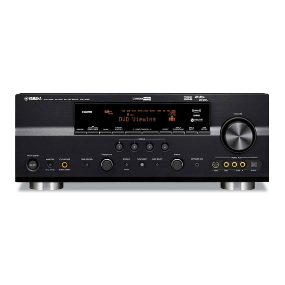
Page 3: Front Panels
RX-V861/HTR-6080/DSP-AX861SE/DSP-AX861 I FRONT PANELS RX-V861 (U, C models) RX-V861 (R, T, K, A, G, E, L models) HTR-6080 (U, C models) - Page 4 RX-V861/HTR-6080/DSP-AX861SE/DSP-AX861 HTR-6080 (G model) DSP-AX861SE (B model) DSP-AX861 (J model)
-
Page 5: Rear Panels
RX-V861/HTR-6080/DSP-AX861SE/DSP-AX861 I REAR PANELS RX-V861 (U, C models) RX-V861 (R model) RX-V861 (T model) - Page 6 RX-V861/HTR-6080/DSP-AX861SE/DSP-AX861 RX-V861 (K model) RX-V861 (A model) RX-V861 (G, E models)
- Page 7 RX-V861/HTR-6080/DSP-AX861SE/DSP-AX861 RX-V861 (L model) HTR-6080 (U, C models) HTR-6080 (G model)
- Page 8 RX-V861/HTR-6080/DSP-AX861SE/DSP-AX861 DSP-AX861SE (B model) DSP-AX861 (J model)
-
Page 9: Remote Control Panels
RX-V861/HTR-6080/DSP-AX861SE/DSP-AX861 I REMOTE CONTROL PANELS • RAV326 • RAV327 • RAV364 RX-V861 (U, C models) RX-V861 (R, T, A, L models) RX-V861 (K, G, E models) HTR-6080 (U, C models) DSP-AX861 (J model) HTR-6080 (G model) DSP-AX861SE (B model) -
Page 10: Specifications
................1.0 V / 1.2 k-ohms Signal to Noise Ratio / (IHF) [RX-V861 (U, C, R, T, K, A, G, E, L models)/HTR-6080 (G model)] Mono / Stereo ............. 73 dB / 70 dB ZONE2 OUT ..........200 mV / 1.2 k-ohms... - Page 11 A model ..............AC 240 V, 50 Hz DVR Viewing MOVIE Drama B, G, E models ............AC 230 V, 50 Hz “SILENT CINEMA” is a trademark of YAMAHA CORPORATION. L model ..........AC 220/230-240 V, 50/60 Hz Disc Hi-fi Listening DVDA/SACD/CD Music Disc PURE DIRECT –...
- Page 12 RX-V861/HTR-6080/DSP-AX861SE/DSP-AX861...
-
Page 13: Internal View
FUNCTION (1) P.C.B. HDMI P.C.B. DSP P.C.B. FUNCTION (2) P.C.B. MAIN (1) P.C.B. FUNCTION (3) P.C.B. • Front view OPERATION (2) P.C.B. OPERATION (5) P.C.B. (RX-V861 / HTR-6080: G model) OPERATION (3) P.C.B. OPERATION (1) P.C.B. OPERATION (4) P.C.B. OPERATION (6) P.C.B. -
Page 14: Disassembly Procedures
RX-V861/HTR-6080/DSP-AX861SE/DSP-AX861 I DISASSEMBLY PROCEDURES (Remove parts in the order as numbered.) Disconnect the power cable from the AC outlet. 1. Removal of Top Cover a. Remove 4 screws (1), 4 screws (2) and screw (3). (Fig. 1) b. Slide the top cover rearward to remove it. (Fig. 1) 2. - Page 15 RX-V861/HTR-6080/DSP-AX861SE/DSP-AX861 4. Removal of DSP and HDMI P.C.B.s a. Remove screw (8) and 2 screws (9). (Fig. 2) b. Remove support PCB-DH. (Fig. 2) c. Remove 7 screws (0). (Fig. 3) d. Remove CB43, CB47, CB49, CB61 and CB62. (Fig. 2) e.
- Page 16 RX-V861/HTR-6080/DSP-AX861SE/DSP-AX861 When checking the P.C.B.: • Put the rubber sheet and cloth over the equipment. Then place the DSP P.C.B. upside down on the cloth and check it. (Fig. 4) • Reconnect all cables (connectors) that have been disconnected. •...
- Page 17 B model HTR-6080 (G model) a. Remove 2 screws (B). (Fig. 5) b. Remove 10 screws (RX-V861 / HTR-6080: G model / DSP-AX861SE) / 9 screws (HTR-6080: U, C models) (C). (Fig. 6) c. Remove CB202, CB206, CB231, CB232 and CB242 (U, C, R, T, K, A, G, E, L models).
- Page 18 RX-V861/HTR-6080/DSP-AX861SE/DSP-AX861 8. Removal of Amp Unit a. Remove screw (F) and screw (G). (Fig. 6) b. Remove 3 screws (H). (Fig. 9) c. Remove CB100, CB101, CB258, CB263, CB254 (R, L models) and CB255 (R, L models). (Fig. 8) d. Remove the MAIN (2), FUNCTION (4) and (5) (R, L models) P.C.B.s together with rear panel.
- Page 19 RX-V861/HTR-6080/DSP-AX861SE/DSP-AX861 When checking the P.C.B.: • Put the rubber sheet and cloth over the equipment. Then place the each amp unit upside down on the cloth and check it. (Fig. 11) • Reconnect all cables (connectors) that have been disconnected.
-
Page 20: Updating Firmware
RX-V861/HTR-6080/DSP-AX861SE/DSP-AX861 I UPDATING FIRMWARE / After replacing the DSP P.C.B., VIDEO P.C.B. and micro- processor (IC301) on the VIDEO P.C.B. with the replace- ment parts, update the firmware according to the following procedure. The TI flash ROM (IC51) on the DSP P.C.B. is not sup- plied as a replacement part. - Page 21 RX-V861/HTR-6080/DSP-AX861SE/DSP-AX861 3. Connect the writing port of the main unit to the se- rial port (RS232C) of the PC with RS232C cross cable, RS232C conversion adapter and flexible flat cable as shown below. (Fig. 1) Writing port / Rear panel...
- Page 22 RX-V861/HTR-6080/DSP-AX861SE/DSP-AX861 When the “Timeout” error is displayed: Press the [Cancel] button and check the following items again. a. Is the power cable of the main unit connected to the AC outlet? b. Reconnect cables, etc. being used in Step 3 of the operation procedure and start “Flash...
- Page 23 RX-V861/HTR-6080/DSP-AX861SE/DSP-AX861 10. Press the [E.P.R...] button, and “Erase OK?” is displayed. (Fig. 4) Press the [OK] button and start writing. (Fig. 4) 11. When writing is completed, “Program Finished” is displayed. (Fig. 4) Press the [OK] button. (Fig. 4) 12. Disconnect the power cable of main unit from the AC outlet.
- Page 24 RX-V861/HTR-6080/DSP-AX861SE/DSP-AX861 1. Reconnect the power cable of main unit to the AC outlet. 2. Press the “MASTER ON/OFF” (RX-V861 / HTR- 6080: G model) / “STANDBY/ON” (HTR-6080: U, C models / DSP-AX861SE / DSP-AX861) key while simultaneously pressing the “STRAIGHT” and “AU- DIO SELECT”...
- Page 25 RX-V861/HTR-6080/DSP-AX861SE/DSP-AX861 Writing to DSP 1. Turn off the power of main unit and disconnect the power cable from the AC outlet. 2. Set the switch (SW301) of RS232C conversion adapter to the “OTHER” side. (Fig. 6) 3. Connect the writing port of the main unit to the serial...
- Page 26 [RDY] button Fig. 8 7. Reconnect the power cable of main unit to the AC outlet. 8. Press the “MASTER ON/OFF” (RX-V861 / HTR-6080: G model) / “STANDBY/ON” (HTR-6080: U, C models / DSP-AX861SE / DSP-AX861) key while simulta- neously pressing “STRAIGHT” and “AUDIO SELECT”...
- Page 27 RX-V861/HTR-6080/DSP-AX861SE/DSP-AX861 11. When writing is completed, “Vx61 DSP Flash finished!” is displayed. (Fig. 10) Then, check the version and checksum of the firmware without turning off the power of the main unit. 12. Select the DIAG menu “23-5. TI FLASH version”. (Fig. 10) Check the displayed firmware version is the same as the written firmware version.
- Page 28 RX-V861/HTR-6080/DSP-AX861SE/DSP-AX861 I SELF DIAGNOSIS FUNCTION (DIAG) This unit has self diagnosis functions that are intended for inspection, measurement and location of faulty point. There are 24 DIAG menu items, each of which has sub- menu items. Listed in the table below are menu items and sub-menu items.
- Page 29 RX-V861/HTR-6080/DSP-AX861SE/DSP-AX861 DIAG menu Sub-menu HDMI INFORMATION 1. HMN 2. HPI 3. HVN HDMI SELECT 1. HDMI NONE 2. HDMI IN 1 3. HDMI IN 2 4. HDMI UPCONV. 5. HDMI UP THR IF STATUS 1. DST 2. DMD 3. DIF 4.
- Page 30 If setting is at “2ch Stereo” when the DIAG function is activated, “SURROUND BACK L/R” and “EXTRA SP L/R” may fail to turn on. Press the “MASTER ON/OFF” (RX-V861 / HTR-6080: G model) / “STANDBY/ON” (HTR-6080: U, C models / DSP-AX861SE / DSP-AX861) key while simulta- neously pressing those two keys of the main unit as indicated in the figure below.
- Page 31 PRESET INHIBITED (Memory ini- tialization inhibited). 2. Turn off the power by pressing the “MASTER ON/OFF” (RX-V861 / HTR-6080: G model) / “STANDBY/ON” (HTR-6080: U, C models / DSP-AX861SE / DSP-AX861) key of the main unit. •...
- Page 32 To avoid this, if protection function has been activated 3 times continuously, the power will not turn on even when the “MASTER ON/OFF” (RX-V861 / HTR- 6080: G model) / “STANDBY/ON” (HTR-6080: U, C models / DSP-AX861SE) key is pressed. In order...
- Page 33 RX-V861/HTR-6080/DSP-AX861SE/DSP-AX861 When there is a history of protection function due to abnormal voltage in the power supply section DC PRT :xxx G Cause: The voltage in the power supply section is abnormal. Supplementary information: The protection function worked due to a de- fect or overload in the power supply.
- Page 34 RX-V861/HTR-6080/DSP-AX861SE/DSP-AX861 • Operation procedure of DIAG menu and Sub-menu There are 24 menu items, each of having sub-menu items. DIAG menu selection: Select the menu using “PROGRAM” knob. Sub-menu selection: Select the sub-menu using “SCENE 2” (forward) / “SCENE 1” (reverse) keys or “PRESET/TUNING >” (forward) / “PRESET/TUNING <”...
- Page 35 RX-V861/HTR-6080/DSP-AX861SE/DSP-AX861 • Details of DIAG menu 1. BYPASS Using the sub-menu, it is possible to select ANALOG BYPASS output or DSP BYPASS output. ANALOG BYPASS The analog input audio signal is output to FRONT L/R by PURE DIRECT. 1.ANALOG BYPAS...
- Page 36 RX-V861/HTR-6080/DSP-AX861SE/DSP-AX861 2. RAM THROUGH Using the sub-menu, it is possible to select MARGIN output or FULL BIT output. RAM MARGIN The signal is output including the head margin. 2.RAM MARGIN FRONT L/R CENTER SURROUND L/R SURROUND BACK L/R SUBWOOFER +9.0 dB +13.5 dB...
- Page 37 RX-V861/HTR-6080/DSP-AX861SE/DSP-AX861 3. HDMI AUDIO The audio signals input to HDMI IN are selected by the sub-menu and output. * When selecting “DSD” be sure to connect an HDMI unit with DSD output function. SPDIF 3.SPDIF SPDIF signal is output. Multi (DVD-Audio) 3.Multi...
- Page 38 RX-V861/HTR-6080/DSP-AX861SE/DSP-AX861 FRONT: SML 0dB 4.FRNT:SML 0dB 90 Hz or lower signal is mixed to the channel specified by LFE/BASS and output. CENTER: NONE 4.CENTER:NONE The CENTER signal is assigned to FRONT L/R. LFE / BASS: FRONT 4.LFE/B:FRNT The LFE/BASS signal is assigned to FRONT L/R.
- Page 39 RX-V861/HTR-6080/DSP-AX861SE/DSP-AX861 5. XCH-INPUT The input source “MULTI CHANNEL INPUT” is se- lected. It is possible to select the 6 ch/8 ch and 6-ohm/8-ohm by using the sub-menu. 6 ch INPUT 6-ohm 5.6CH INPUT_6 Ω INPUT: MULTI CH INPUT SPEAKER OUT: 1 kHz, SUBWOOFER OUTPUT: 50 Hz...
- Page 40 RX-V861/HTR-6080/DSP-AX861SE/DSP-AX861 LIM / PLDET / THM LIM: Setting value of LIM (Limiter control) * As this is a development menu, do not change the setting value. PLDET: Power limiter detection The A/D conversion value during operation is displayed. (Reference voltage: 5.0 V=255)
- Page 41 RX-V861/HTR-6080/DSP-AX861SE/DSP-AX861 Checking FL display section / Check of the Video control section. (Monitor out) / Initial display / Initial display (OSD OFF) / All segments OFF / OSD OFF / All segments ON (dimmer 100 %) / OSD characters ON /...
- Page 42 RX-V861/HTR-6080/DSP-AX861SE/DSP-AX861 8. MANUAL TEST Noise is output to all channels through the noise gen- eration circuit which is included in the microprocessor. The noise frequency for LFE (SUBWOOFER) is 35 to 80 Hz. Other than that, the noise frequency is 500 to 2 kHz.
- Page 43 RX-V861/HTR-6080/DSP-AX861SE/DSP-AX861 10. A/D DATA CHECK This menu is used to display the A/D conversion value of the microprocessor which detects panel keys of the main unit and protection functions in using the sub- menu. During signal processing, the condition before execu- tion is maintained.
- Page 44 PLDET (8-ohm/6-ohm) 255 / 255 LIM (Limiter control) K0/K1 K0:100 K1:100 RX-V861 (U, C, R, T, K, A, G, E, L models) / HTR-6080 (G model) HTR-6080 (U, C models) / DSP-AX861 (J model) Display / KEY0 KEY1 Display /...
- Page 45 RX-V861/HTR-6080/DSP-AX861SE/DSP-AX861 11. VIDEO CHECK The video circuit is checked by the sub-menu opera- tion. I2C (Inter integrated circuit) read/write check Self-diagnosis is executed to check whether data reading/writing between the microprocessor con- nected to the 12C line and each IC is done properly or not.
- Page 46 RX-V861/HTR-6080/DSP-AX861SE/DSP-AX861 Digital Y/C (S-Video) The signal passage as shown below is checked. DIGITAL Y/C Digital Y/C (S Video) HDMI HDMI IC14 HDMI SII9033CTU SII9030CTU IC27 ABT1010 I/P SCALAR HDMI HDMI IC13 ADV7401 ADV7172 VIDEO VIDEO VIDEO DECODER ENCODER IC358 S Video...
- Page 47 RX-V861/HTR-6080/DSP-AX861SE/DSP-AX861 Video information Displays the information of image signals being input. Example / VIDEO IN 480p 12. XM STATUS (U, C models) The output check of XM radio antenna module is ex- ecuted. 1 kHz, -1 dB / 44.1 kHz 1k - 1dB/44 The test tone (1 kHz, -1 dB / 44.1 kHz) is output.
- Page 48 RX-V861/HTR-6080/DSP-AX861SE/DSP-AX861 13. DOCK This menu is used to test the DOCK connector without the iPod itself. After turning off the power, short between pins No. 14 (TX) and No. 18 (RX), between pins No. 1 (PWR) and No. 17 (ACCPOW) and between pins No. 4 (iPDET) and No.
- Page 49 The product ID of main unit written in HDMI module is displayed. 311F: U, C, R, T, K, A, B, G, E, L models 311E: J model HDMI vendor name HVN:YAMAHA The vendor name “YAMAHA” of main unit written in HDMI module is displayed.
- Page 50 RX-V861/HTR-6080/DSP-AX861SE/DSP-AX861 17. HDMI SELECT The selected input signal is output to HDMI OUT by the sub-menu operation. * Support audio is set to “OTHER”. HDMI none HDMI NONE No signal is output. HDMI in 1 HDMI IN 1 HDMI “IN 1” is output.
- Page 51 RX-V861/HTR-6080/DSP-AX861SE/DSP-AX861 18. IF STATUS (Input function status) The status information is displayed in the hexadeci- mal notation one after another by the sub-menu op- eration. For signal processing, the status before the sub-menu operation is maintained. * The details of the following status information cannot be disclosed because of the development purpose.
- Page 52 RX-V861/HTR-6080/DSP-AX861SE/DSP-AX861 20. PROTECTION SETTING The A/D setting value of each protection is displayed. (Reference voltage: 5.0 V=255) * The figures in the diagram are given as reference only. PS1 (Power supply protection 1) Low PS1_Lo: 0111 The minimum preset value of PS1 is displayed.
- Page 53 RX-V861/HTR-6080/DSP-AX861SE/DSP-AX861 21. PROTECTION HISTORY Four protection histories are displayed. Example / History 1 / 21-1.DcPRT 000 Example / History 2 / 21-2.P1PRT:061 Example / History 3 / 21-3.TmPRT:000 Example / History 4 / 21-4.NoPRT...
- Page 54 RX-V861/HTR-6080/DSP-AX861SE/DSP-AX861 22. SOFT SWITCH Note) As this is a development menu, do not change the function setting. Changing the function setting may hinder the proper operation. This menu is used to switch the function settings on P.C.B. through the software to activate the main unit.
- Page 55 RX-V861/HTR-6080/DSP-AX861SE/DSP-AX861 23. ROM VER. / SUM / PORT The version and checksum are displayed. The signal is processed using EFFECT OFF. The checksum is obtained by adding the data at every 8-bit for each program area and expressing the result as a 4-figure hexadecimal data.
-
Page 56: Confirmation Of Idling Current Of Amp Unit
RX-V861/HTR-6080/DSP-AX861SE/DSP-AX861 I CONFIRMATION OF IDLING CURRENT OF AMP UNIT • Right after power is turned on, confirm that the voltage across the terminals of R1303 (SURROUND BACK R ch), R1153 (SURROUND R ch), R1154 (FRONT R ch), R1152 (CEN- TER), R1150 (FRONT L ch), R1151 (SURROUND L ch), R1149 (SURROUND BACK L ch) are between 0.1 mV and... -
Page 57: Display Data
RX-V861/HTR-6080/DSP-AX861SE/DSP-AX861 I DISPLAY DATA G V401: 17-BT-29GNK (OPERATION P.C.B.) G ANODE CONNECTION 13G~1G PATTERN AREA G PIN CONNECTION Pin No. 68 67 Connection F2 NX Pin No. Connection Note : 1) F1, F2 ..Filament pin 2) NP ..No pin 3) NX .. - Page 58 RX-V861/HTR-6080/DSP-AX861SE/DSP-AX861 I IC DATA IC41: LC89057W-VF4AD-E (DSP P.C.B.) Pin No. Function Name Detail of Function Digital audio interface transceiver EMPHA/UO AUDIO/VO XMODE Microcontroller RXOUT Cbit, Ubit RERR Demodulation Input Data & RDATA Selector Selector Lock detect RX5/VI SDIN RX6/UI RMCK...
- Page 59 RX-V861/HTR-6080/DSP-AX861SE/DSP-AX861 IC44 : D70YE101BRFP266 (DSP P.C.B.) Floating-point digital signal processors * No replacement part available. / Program/Data JTAG EMU 256K Bytes McASP0 Data 16 Serializers Program/Data ROM Page1 C67x + Microprocessor 256K Bytes Memory Data Controller Program/Data McASP1 ROM Page2...
- Page 60 RX-V861/HTR-6080/DSP-AX861SE/DSP-AX861 Function Name Detail of Function TYPE PULL GPIO External memory interface (EMIF) address and control EM_CAS – SDRAM column address strobe EM_WE – SDRAM write enable EM_WE_DQM[0] – Write enable or byte enable for EM_D[7:0] EM_WE_DQM[1] – Write enable or byte enable for EM_D[15:8] EM_CLK –...
- Page 61 RX-V861/HTR-6080/DSP-AX861SE/DSP-AX861 Function Name Detail of Function TYPE PULL GPIO AXR0[3] – McASP0 serial data 3 AXR0[4] – McASP0 serial data 4 SPI1_SCS – McASP0 serial data 5 or SPI1 slave chip select SPI1_ENA – McASP0 serial data 6 or SPI1 enable (Ready) SPI1_CLK –...
- Page 62 RX-V861/HTR-6080/DSP-AX861SE/DSP-AX861 Function Name Detail of Function TYPE PULL GPIO CVDD Core supply DVDD I/O supply Ground 1) TYPE column refers to pin direction in functional mode. If a pin has more than one function with different directions, the functions are separated with a slash (/).
- Page 63 RX-V861/HTR-6080/DSP-AX861SE/DSP-AX861 IC202 : R2A15215FP (FUNCTION P.C.B.) 8 ch electronic volume with 11 input selector and tone control 49 48 46 45 38 37 34 33 A VCC A VCC MUTE N.C. A VEE A VEE N.C. TREL 0/-6/-12/-18dB ADCL BASSL2...
- Page 64 RX-V861/HTR-6080/DSP-AX861SE/DSP-AX861 Pin No. Function Name Detail of Function SBLC Connects capacitor for reducing click noise of L/R/C/SW/SL/SR/SBL/SBR channel volume SBL OUT Output pin of FL/FR/C/SW/SL/SR/SBL/SBR channel AGND Analog ground of internal circuit SBR OUT Output pin of FL/FR/C/SW/SL/SR/SBL/SBR channel SBRC...
- Page 65 RX-V861/HTR-6080/DSP-AX861SE/DSP-AX861 Pin No. Function Name Detail of Function MUTE Outside mute control pin AVEE Negative power supply to internal circuit ADCL Output pin for L/R channel ADC ADCR AGND Analog ground of internal circuit INR1 INL1 INR2 INL2 INR3 INL3...
- Page 66 RX-V861/HTR-6080/DSP-AX861SE/DSP-AX861 IC401 : M66003-0131FP (OPERATION P.C.B.) FL display driver Display code CGROM SEG00 (35 bit x 166) (8-bit x 60) Segment SEG25 Code output write SEG26 circuit CGROM SEG34 Serial dot data data (35 bit x 16) write receive Code/...
- Page 67 RX-V861/HTR-6080/DSP-AX861SE/DSP-AX861 Pin No. Port Name Function Name Detail of Function RESET /RESET Reset input When “L”, M66003 is initialized. /CEFL Chip select input When “L”, communication with the MCU is possible. CKFL Shift clock input When “H”, any instruction from the MCU is neglected.
- Page 68 RX-V861/HTR-6080/DSP-AX861SE/DSP-AX861 IC301 : M30878JBGP (VIDEO P.C.B.) Single chip 16/32-bit microprocessor Port P0 Port P1 Port P2 Port P3 Port P4 Port P5 Port P6 < > < > Peripheral Functions Clock Generation Circuit A/D Converter: 1 circuit Timer (16-bit) Standard: 10 inputs...
- Page 69 RX-V861/HTR-6080/DSP-AX861SE/DSP-AX861 Function Name Port Name Detail of Function (P.C.B.) TXD4 TXDi Asynchronous data output for iPod /NW_RST Limiter control output TB3in iPDET iPod DOCK installation detection TXD3 DTXM Asynchronous data output for XM/DT IC (U, C models) (TXDRDS/RDYRDS) READY input for new RDS IC (G, E models)
- Page 70 RX-V861/HTR-6080/DSP-AX861SE/DSP-AX861 Function Name Port Name Detail of Function (P.C.B.) Vcc2 Vcc2 Microprocessor power +5BU [Vcc] P131 /RES_TX Reset output for HDMI Tx IC, pull-down by HDMI P.C.B. P130 DP_SEL DSD/ PCM select CVBS/S input select A CVBS/S input select B...
- Page 71 RXDi Asynchronous data input for iPod Key detection for AD port Key input (A/D) pull-up resistance 10 k-ohms RX-V861 (U, C, R, T, K, A, G, E, L models), HTR-6080 (G model) +1.0 k +1.0 k +1.5 k +2.2 k +3.3 k...
- Page 72 RX-V861/HTR-6080/DSP-AX861SE/DSP-AX861 I PIN CONNECTION DIAGRAMS • ICs ABT1010PQ100A ADV7172KST ADV7401BSTZ-80 D70YE101BRFP266 M30878JBGP AD8056AR BA15218F CD4051BNSR F2621E-01-TR KIA7805API LA7106M-TLM-E LA73050-TLM-E EN29L400AB-70TC LC74782JM-8A16-TLMC LC72725KM-UY-TLM-E S29AL004D7 MM74HC4053SJX PCM1780DBQR PCM1781DBQR LC89057W-VF4AD-E LM61CIZ M66003-0131FP-R NJM2068MD-TE2 M24C02-WMN6TP NJM2388F33 NJM2391DL1-33 NJM2396F63 NJM2581M NJM2867F3-05 NJM2388F05 TC7SET32FU 2:GND 1. V 2.
- Page 73 RX-V861/HTR-6080/DSP-AX861SE/DSP-AX861 PCM1680DBQR PCM1803DBR R2A15215FP R1131N181D R1172S121D-E2-F TC7WZ32FK (TE85L, F) TA1318AF R1172H331D-T1-F RH5RE58AA-T1-FA TC4013BP 1: CE 2: GND 3: NC 1: Vin 2: GND 4: V 5: V 3: Vout TC74VHC153FT TC74VHCT08AFT TC7SH04FU-TE85L TC74HC4051AFEL TC74VHCU04FT (EL) TC74VHC157FT TC74HC4052AF TC74VHC157FT SII9030CTU-7 SII9033CTU...
- Page 74 RX-V861/HTR-6080/DSP-AX861SE/DSP-AX861 • Diodes 1N4002S 1SS355 DB105 MA8030-L 2.9V 1SS133 1SS380 MA8051-M 5.1V 1SS176 UDZ3.6BTE-17 3.6V MA8056-M 5.6V 1SS270A MA8068-M 6.8V UDZ5.1B MA8075-H 7.7V MA8091 9.1V Anode MA8091-M 9.1V Anode Anode – MA8100-M 10.0V MA8100-H 10.3V Cathode Cathode Cathode MA8024-(TX) 2.4V MTZJ2.4B...
- Page 75 RX-V861/HTR-6080/DSP-AX861SE/DSP-AX861 • Transistors 2N5401C-AT/P 2N5551C-AT 2SA949 2SA1708 2SA1015-Y (TPE2,F) 2SC1815 2N5401C-AT 2SC1890A 2SC2229 1: Emitter 2: Collector 3: Base 2SA1037K 2SA1695 O,P,Y 2SB1257 2SC1740S 2SA1770S/T-AN 2SA1576A 2SC4468 O,P,Y 2SD2014 1: Base 1: Emitter 1: Base 2: Collector 2: Collector 2: Collector...
- Page 76 AUDIO (DIGITAL) SECTION BLOCK DIAGRAM • See page 97, 98 → U, C models XMSDO XMDT IC SCHEMATIC DIAGRAM F2621E-01-TR XMWCK IC42 XMBCK XMMCK RX-V861 (U, C models) PCM1781 2ch DAC OPERATION IC61 PCM1803 RMCK Normal Phase SCKI MIC IN MIC in...
- Page 77 RX-V861/HTR-6080/DSP-AX861SE/DSP-AX861 AUDIO (ANALOG) SECTION BLOCK DIAGRAM • See page 97, 98 → To AUDIO (DIGITAL) Section Block Diagram SCHEMATIC DIAGRAM XML/XMR R, T, K, A, B, G, E, L, J models iPL/iPR DOCK (iPod) FRONT L/R U, C, R, T, K, A, G, E, L, J models...
- Page 78 RX-V861/HTR-6080/DSP-AX861SE/DSP-AX861 VIDEO / HDMI SECTION BLOCK DIAGRAM • See page 103-105 → SCHEMATIC DIAGRAM • See page 106, 107 → SCHEMATIC DIAGRAM VIDEO HDMI SDAL SCLL IC301 SVDET S2DET 27,28 L3DET SCLH 43,44 CSCL CSCL /INTH_RT SDAH HDMI HDMI SCLH...
- Page 79 RX-V861/HTR-6080/DSP-AX861SE/DSP-AX861 CONTROL/POWER SUPPLY SECTION BLOCK DIAGRAM POWER /4ohms TRANSFORMER ACBL RY105 ACBH OPERATION VIDEO MAIN • See page 101 → • See page 103-105 → • See page 102 → SCHEMATIC DIAGRAM SCHEMATIC DIAGRAM SCHEMATIC DIAGRAM ACDH LIMITER CONTROL RY105...
- Page 80 CB61 CB46 D402 D403 DOCK D409 D411 D601 D603 U, C models D604 U, C models D607 IC54 IC55 RX-V861 (U, C models) D608 IC42 D609 IC63 D610 IC72 D611 IC41 IC42 IC43 U, C models IC44 IC67 IC45 MD/CD-R...
- Page 81 RX-V861/HTR-6080/DSP-AX861SE/DSP-AX861 DSP P.C.B. (Side B) R, T, K, A, B, G, E, L, J models U, C models RX-V861 (U, C models) • Semiconductor Location Ref no. Location D406 D605 D606 D612 D613 U, C models Q404 Q601 RX-V861 (U, C models)
- Page 82 RX-V861/HTR-6080/DSP-AX861SE/DSP-AX861 FUNCTION (1) P.C.B. (Side A) RX-V861, B model HTR-6080 (G model) AUDIO MULTI CH INPUT ZONE 2 PRE OUT PHONO MD/CD-R DTV/CBL TUNER FRONT SURROUND CENTER / FRONT SURROUND SINGLE / CENTER / SUBWOOFER SUR. BACK SUBWOOFER IN (PLAY)
- Page 83 RX-V861/HTR-6080/DSP-AX861SE/DSP-AX861 FUNCTION (1) P.C.B. (Side B) RX-V861, HTR-6080 (G model) B model IC225 IC201 U, C, R, T, K, A, G, E, L, J models IC226 IC227 G, E models IC241 IC220 R, T, K, A, B, G, E, L, J models •...
- Page 84 RX-V861/HTR-6080/DSP-AX861SE/DSP-AX861 FUNCTION (2) P.C.B. (Side A) U, C models IC255 IC252 IC256 IC262 IC251 IC258 IC253 IC250 (CB62) PRV2 +3.3D XMPWR +IPOD +5.3X XGND IGND W2504A VPWR CB250 W2501 W2502 MAIN (2) (W100) VIDEO (CB351) HDMI (CB7) FUNCTION (3) P.C.B.
- Page 85 RX-V861/HTR-6080/DSP-AX861SE/DSP-AX861 FUNCTION (4) P.C.B. (Side B) FUNCTION (5) P.C.B. FUNCTION (4) P.C.B. (Side A) (Side A) R, L models AC IN POWER TRANSFORMER (U, C, T, K, A, B, G, E, J models) VOLTAGE POWER TRANSFORMER SELECTOR (R, L models)
- Page 86 RX-V861/HTR-6080/DSP-AX861SE/DSP-AX861 OPERATION (1) P.C.B. (Side A) OPERATION (2) (CB426) MASW VIDEO U, C, R, T, K, A, G, E, L, J models (CB301) RX-V861, HTR-6080 (G model) B model MASTER SCKN SDTN /CEFD SCEN2 SCEN1 SCEN0 ADKEY1 ADKEY0 TONEB TONEA...
- Page 87 RX-V861/HTR-6080/DSP-AX861SE/DSP-AX861 OPERATION (1) P.C.B. (Side B) RX-V861, HTR-6080 (G model) IC402 U, C, R, T, K, A, G, E, L, J models RX-V861, HTR-6080 (U, C models), HTR-6080 (G model) DSP-AX861SE, DSP-AX861 • Semiconductor Location Ref no. Location Ref no. Location Ref no. Location Ref no. Location Ref no.
- Page 88 RX-V861/HTR-6080/DSP-AX861SE/DSP-AX861 OPERATION (3) P.C.B. OPERATION (3) P.C.B. (Side A) (Side B) OPERATION (2) P.C.B. (Side A) PHONES SILENT CINEMA RX-V861, MAIN ZONE HTR-6080 (G model) JK431 ON/OFF HTR-6080 (U, C models), STANDBY/ON DSP-AX861SE, DSP-AX861 OPERATION (1) (W404) CB426 CB452 OPERATION (1)
- Page 89 RX-V861/HTR-6080/DSP-AX861SE/DSP-AX861 OPERATION (5) P.C.B. (Side A) OPERATION (4) P.C.B. (Side A) FUNCTION (1) (CB201) RX-V861, (CB46) OPERATION (1) (W403) HTR-6080 (G model) W442 W441 CB451 MASTER JK441 OPTICAL AUDIO VIDEO S VIDEO VIDEO AUX OPERATION (6) P.C.B. (Side A) OPERATION (1) OPERATION (4) P.C.B.
- Page 90 RX-V861/HTR-6080/DSP-AX861SE/DSP-AX861 MAIN (1) P.C.B. (Side A) VIDEO FUNCTION (1) MAIN (2) MAIN (2) MAIN (2) MAIN (2) MAIN (2) FUNCTION (1) MAIN (2) MAIN (2) MAIN (2) MAIN (2) (CB304) (CB231) (W108B) (W120B) (W110B) (W112B) (W114B) (CB232) (W115B)(W115D) (W109B) (W109B)
- Page 91 RX-V861/HTR-6080/DSP-AX861SE/DSP-AX861 MAIN (2) P.C.B. (Side A) SPEAKERS FRONT B/ZONE 2 / FRONT A CENTER SURROUND SURROUND BACK/BI-AMP PRESENCE L (SINGLE) + / - + / - + / - + / - + / - + / - + / -...
- Page 92 RX-V861/HTR-6080/DSP-AX861SE/DSP-AX861 VIDEO P.C.B. (Side A) WRITING PORT J model • Semiconductor D4 VIDEO COMPONENT VIDEO VIDEO MONITOR Location DTV/CBL DVD / MONITOR OUT DTV/CBL / DVR DTV/CBL MONITOR OUT Ref no. Location VIDEO/S VIDEO D3001 D3002 D3006 D3007 D3008 D3009...
- Page 93 RX-V861/HTR-6080/DSP-AX861SE/DSP-AX861 VIDEO P.C.B. (Side B) U, C, J models R model CB381 CB382 CB383 CB384 JK351 JK352 JK353 CB309 J model IC388 IC351 IC352 IC381 IC353 IC355 IC386 IC382 IC383 IC387 IC384 IC356 IC357 IC385 IC389 CB307 IC358 IC359 W3502 •...
- Page 94 RX-V861/HTR-6080/DSP-AX861SE/DSP-AX861 HDMI P.C.B. (Side A) • Semiconductor Location VIDEO (CB352) Ref no. Location Ref no. Location Ref no. Location Ref no. Location VIDEO (CB308) (CB47) D280 FUNCTION (2) IC22 IC25 (W2502) +5.0HV HGND HGND HGND +6.3H IC14 IC33 IC32 DTV/CBL...
- Page 95 RX-V861/HTR-6080/DSP-AX861SE/DSP-AX861 HDMI P.C.B. (Side B) • Semiconductor Location Ref no. Location Ref no. Location Ref no. Location Ref no. Location...
- Page 96 RX-V861/HTR-6080/DSP-AX861SE/DSP-AX861 MEMO MEMO MEMO MEMO...
- Page 97 RX-V861/HTR-6080/DSP-AX861SE/DSP-AX861 SCHEMATIC DIAGRAMS DSP 1/2 Page 103 Page 101 Page 107 Page 1054 to VIDEO_W3501 to OPERATION (4)_W442 to HDMI_CB4 to VIDEO_CB306 IC49: W9816G6CH-7 512 K x 2 banks x 16-bit SDRAM CLK 35 CLOCK BUFFER CKE 34 COLUMN DECODER...
- Page 98 Low-Pass Filter IC70 System Clock AGND DGND System Clock 2, 6 Zero Detect Power Supply Manager -11.3 –INPUT OUTPUT 1, 7 +INPUT RX-V861 (U, C models) MODE1 3, 5 MODE0 FMT1 FMT0 AGND SCKI PDWN V– BYPAS DGND TEST DOUT LRCK IC72 11.6...
- Page 99 RX-V861/HTR-6080/DSP-AX861SE/DSP-AX861 FUNCTION 1/2 Interchangeable Parts at Manufacture-Stage Mark Reference Parts Number Parts Name &1 D2301, 2302, 2403, 2404, 2508-2510, 1SS355 2514, 2517 MA111 KDS160-RTK/P &2 IC259, 261 TLP421GR EL816 [B] &3 Q2510 K3850-E 2SK3491-E &4 D2516, 2518 DB105 S1NB60 &5...
- Page 100 RX-V861/HTR-6080/DSP-AX861SE/DSP-AX861 FUNCTION 2/2 Destination Part List DSP-AX861 RX-V861/HTR-6080/DSP-AX861SE C2537 WJ36120 WJ36120 WJ36180 WJ36180 WJ36180 WJ36180 WJ36180 WJ36180 WJ36180 WJ36180 0.047/400 0.047/400 0.022/630 0.022/630 0.022/630 0.022/630 0.022/630 0.022/630 0.022/630 0.022/630 C2541 WB69630 WB69630 WD25760 WD25760 WD25760 WD25760 WD25760 WD25760 WD25760 WD25760 0.1/400...
- Page 101 Key input (A/D) pull-up resistance 10 k-ohms CGROM SEG34 Serial dot data (35-bit x 16) data write RX-V861 (U, C, R, T, K, A, G, E, L models), HTR-6080 (G model) receive Code/ circuit SDATA command +1.0 k +1.5 k +2.2 k...
- Page 102 RX-V861/HTR-6080/DSP-AX861SE/DSP-AX861 MAIN JK100 57.5 57.4 57.5 57.5 Page 105 JK201 to VIDEO_CB304 11.4 11.4 57.2 -1.0 -0.4 11.4 11.1 -1.0 11.4 W119 W111A W111B JK102 -1.0 -0.5 -0.5 11.4 11.3 -1.0 -57.4 SURROUND -54.2 -57.4 BACK L 10.7 -54.8 -54.9 11.4...
- Page 103 RX-V861/HTR-6080/DSP-AX861SE/DSP-AX861 VIDEO 1/3 Page 107 Page 100 Page 97 Page 99 to HDMI_CB6 to FUNCTION (2)_W2501 to DSP_CB43 to FUNCTION (1)_CB202 IC353: CD4051BNSR Single 8-channel multiplexer CHANNEL IN/OUT V DD † † COMMON BINARY LOGIC OUT/IN 1 OF 8 LEVEL...
- Page 104 RX-V861/HTR-6080/DSP-AX861SE/DSP-AX861 VIDEO 2/3 L1 L2 SELECTOR FREQUENCY COUNTER J model Destination Part List DSP-AX861 RX-V861/DSP-AX861SE HTR-6080 C3804-3815 US06410 to VIDEO 3/3 0.01 (B) C3816-3818 US06080 8P (CH) C3831 US13510 C3834-3836 0.1/16 CB381-384 WD39840 YKF45-3011 D3801-3811 VT33290 D3814-3817 1SS355 IC384 XS790A0...
- Page 105 RX-V861/HTR-6080/DSP-AX861SE/DSP-AX861 VIDEO 3/3 Page 101 Page 102 Page 102 Page 100 Page 99 C-2 C-3 to OPERATION (1)_CB401 to MAIN (2)_W103 to MAIN (1)_W119 to FUNCTION (4)_W2506 to FUNCTION (1)_CB206 CB302 10.0 10.0 IC302: RH5RE58AA-T1-FA Voltage regulator to VIDEO 1/3 -6.2...
- Page 106 RX-V861/HTR-6080/DSP-AX861SE/DSP-AX861 HDMI 1/2 Interchangeable Parts at Manufacture-Stage Mark Reference Parts Number Parts Name &1 D11, 12, 14, 37, 40, 49, 54 1SS355 MA111 KDS160-RTK/P IC8: NJM2867F3-05 Low dropout voltage regulator REGULATOR Control Thermal Protection Bandgap Reference EEPROM 5.0 5.0 IC32: TC74VHC157FT...
- Page 107 RX-V861/HTR-6080/DSP-AX861SE/DSP-AX861 HDMI 2/2 to HDMI 1/2 to HDMI 1/2 to HDMI 1/2 to HDMI 1/2 to HDMI 1/2 to HDMI 1/2 SELECTOR to HDMI 1/2 IC25 IC11 IC12 IC22 Page 97 to DSP_CB47 SCALER D/A ENCODER IC27 IC33 A/D DECODER...
-
Page 108: Replacement Parts List
RX-V861/HTR-6080/DSP-AX861SE/DSP-AX861 I REPLACEMENT PARTS LIST • ELECTRICAL COMPONENT PARTS WARNING G Components having special characteristics are marked s and must be replaced with parts having specifications equal to those originally installed. G The chip resistor is not supplied as a replacement part. - Page 109 RX-V861/HTR-6080/DSP-AX861SE/DSP-AX861 P.C.B. DSP ✻ New Parts...
- Page 110 RX-V861/HTR-6080/DSP-AX861SE/DSP-AX861 P.C.B. DSP ✻ New Parts...
- Page 111 RX-V861/HTR-6080/DSP-AX861SE/DSP-AX861 P.C.B. DSP ✻ New Parts...
- Page 112 RX-V861/HTR-6080/DSP-AX861SE/DSP-AX861 P.C.B. DSP and P.C.B. FUNCTION ✻ New Parts...
- Page 113 RX-V861/HTR-6080/DSP-AX861SE/DSP-AX861 P.C.B. FUNCTION ✻ New Parts...
- Page 114 RX-V861/HTR-6080/DSP-AX861SE/DSP-AX861 P.C.B. FUNCTION ✻ New Parts...
- Page 115 RX-V861/HTR-6080/DSP-AX861SE/DSP-AX861 P.C.B. FUNCTION ✻ New Parts...
- Page 116 RX-V861/HTR-6080/DSP-AX861SE/DSP-AX861 P.C.B. FUNCTION ✻ New Parts...
- Page 117 RX-V861/HTR-6080/DSP-AX861SE/DSP-AX861 P.C.B. FUNCTION ✻ New Parts...
- Page 118 RX-V861/HTR-6080/DSP-AX861SE/DSP-AX861 P.C.B. FUNCTION ✻ New Parts...
- Page 119 RX-V861/HTR-6080/DSP-AX861SE/DSP-AX861 P.C.B. FUNCTION and P.C.B. OPERATION ✻ New Parts...
- Page 120 RX-V861/HTR-6080/DSP-AX861SE/DSP-AX861 P.C.B. OPERATION ✻ New Parts...
- Page 121 RX-V861/HTR-6080/DSP-AX861SE/DSP-AX861 P.C.B. OPERATION and P.C.B. MAIN ✻ New Parts...
- Page 122 RX-V861/HTR-6080/DSP-AX861SE/DSP-AX861 P.C.B. MAIN ✻ New Parts...
- Page 123 RX-V861/HTR-6080/DSP-AX861SE/DSP-AX861 P.C.B. MAIN ✻ New Parts...
- Page 124 RX-V861/HTR-6080/DSP-AX861SE/DSP-AX861 P.C.B. MAIN ✻ New Parts...
- Page 125 RX-V861/HTR-6080/DSP-AX861SE/DSP-AX861 P.C.B. MAIN and P.C.B. VIDEO ✻ New Parts...
- Page 126 RX-V861/HTR-6080/DSP-AX861SE/DSP-AX861 P.C.B. VIDEO ✻ New Parts...
- Page 127 RX-V861/HTR-6080/DSP-AX861SE/DSP-AX861 P.C.B. VIDEO ✻ New Parts...
- Page 128 RX-V861/HTR-6080/DSP-AX861SE/DSP-AX861 P.C.B. VIDEO and P.C.B. HDMI ✻ New Parts...
- Page 129 RX-V861/HTR-6080/DSP-AX861SE/DSP-AX861 P.C.B. HDMI ✻ New Parts...
- Page 130 RX-V861/HTR-6080/DSP-AX861SE/DSP-AX861 P.C.B. HDMI P.C.B. HDMI ✻ New Parts ✻ New Parts...
- Page 131 RX-V861/HTR-6080/DSP-AX861SE/DSP-AX861 • OVERALL ASS’Y T, K, A, B, G, E models R, L models 7 (1) 7 (5) 7 (4) U, C, R, T, K, A, G, E, L, J models AMP Unit Front Panel Unit LEFT U, C, R, K, A,...
- Page 132 RX-V861/HTR-6080/DSP-AX861SE/DSP-AX861 ✻ New Parts ✻ New Parts...
- Page 133 U, C, R, T, K, A, G, E, L, J models 3-103 3-102 3-4 (1) 3-4 (3) 3-101 3-1 (2) 3-102 RX-V861 U, C, R, T, K, A, G, E, L models 3-1 (6) HTR-6080 G model 3-1 (5) 3-102 3-101...
- Page 134 RX-V861/HTR-6080/DSP-AX861SE/DSP-AX861 • AMP UNIT 2-104 2-21 2-104 2-20 2-106 2-104 2-104 2-1 (2) 2-104 2-103 2-101 2-104 2-1 (1) 2-101 2-101 2-11 2-101 2-104 ✻ New Parts...
- Page 135 RX-V861/HTR-6080/DSP-AX861SE/DSP-AX861 I REMOTE CONTROL G RAV326 (U, C models), RAV327 (R, T, A, L, J models) • SCHEMATIC DIAGRAM • PANELS FORMAT : NEC FORMAT RAV326 (U, C models) RAV327 (R, T, A, L, J models) CARRIER FREQ. : 37.9 kHz...
- Page 136 RX-V861/HTR-6080/DSP-AX861SE/DSP-AX861 • KEY LAYOUT • KEY CODE AMP library code Function Label Common ZONE2 MAIN ZONE2 MAIN O (10sec) Linked with IR signal – – – O (10sec) – – Change to PRESET mode CODE SET – – – –...
- Page 137 RX-V861/HTR-6080/DSP-AX861SE/DSP-AX861 G RAV364 (K, B, G, E models) • SCHEMATIC DIAGRAM • PANELS VBAT SOURCE Spring 0028 2006 7017 7002 100n 7011 5002 BC875B BC857B 4 x AAA Batteries 7009 P3.1/... 3019 BC847B 7010 XOUT P3.0/... VBAT 6003 3002 BC847B TEST P2.4/INT9...
- Page 138 RX-V861/HTR-6080/DSP-AX861SE/DSP-AX861 • KEY LAYOUT • KEY CODE AMP library 2002 AMP library 2001 (default) Label Area Learn Macro Luminous MAIN ZONE2 ZONE3 MAIN ZONE2 ZONE3 – – – – – – – – – – – Linked with IR signal...
- Page 139 RX-V861/HTR-6080/DSP-AX861SE/DSP-AX861...
- Page 140 RX-V861/HTR-6080/DSP-AX861SE/DSP-AX861...
- Page 141 RX-V861/HTR-6080/DSP-AX861SE/DSP-AX861 Parts List for Carbon Resistors Value 1/4W Type Part No. 1/6W Type Part No. Value 1/4W Type Part No. 1/6W Type Part No. 1.0 Ω 3100 3100 10 kΩ 7100 7100 HJ35 HF85 HF45 HF45 1.8 Ω ❊ 3180 11 kΩ...
- Page 142 RX-V861/HTR-6080/DSP-AX861SE/DSP-AX861 I SCENE CONTROL • Example of connection RECEIVER/AMPLIFIER DVD/CD PLAYER (Model with SCENE function) (Model with SCENE control signal reception function) REMOTE CONTROL REMOTE CONTROL Monaural analog mini cable • SCENE control Press "STANDBY/ON" / Power relay ON Canceling MUTE function after power ON initialization...
- Page 143 RX-V861/HTR-6080/DSP-AX861SE/ DSP-AX861...