Lincoln Electric LN-25 PRO DUAL POWER Operator's Manual
Hide thumbs
Also See for LN-25 PRO DUAL POWER:
- Operator's manual (45 pages) ,
- Service manual (103 pages) ,
- Operator's manual (43 pages)
Table of Contents
Advertisement
Quick Links
Operator's Manual
LN-25 PRO DUAL POWER
Register your machine:
www.lincolnelectric.com/register
Authorized Service and Distributor Locator:
www.lincolnelectric.com/locator
Save for future reference
Date Purchased
Code:
(ex: 10859)
Serial:
(ex: U1060512345)
IM10079
| Issue D ate 11-Aug
© Lincoln Global, Inc. All Rights Reserved.
For use with machines having Code Numbers:
11749, 11751
Advertisement
Table of Contents

Related Manuals for Lincoln Electric LN-25 PRO DUAL POWER


Summary of Contents for Lincoln Electric LN-25 PRO DUAL POWER
- Page 1 Operator’s Manual LN-25 PRO DUAL POWER For use with machines having Code Numbers: 11749, 11751 Register your machine: www.lincolnelectric.com/register Authorized Service and Distributor Locator: www.lincolnelectric.com/locator Save for future reference Date Purchased Code: (ex: 10859) Serial: (ex: U1060512345) IM10079 | Issue D ate 11-Aug...
- Page 2 351040, Miami, Florida 33135 or CSA Standard W117.2-1974. A Free copy of “Arc Welding Safety” booklet E205 is available from the Lincoln Electric Company, 22801 St. Clair Avenue, Cleveland, Ohio 44117-1199. BE SURE THAT ALL INSTALLATION, OPERATION, MAINTENANCE AND REPAIR PROCEDURES ARE PERFORMED ONLY BY QUALIFIED INDIVIDUALS.
-
Page 3: Electric Shock Can Kill
SAFETY ARC RAYS can burn. ELECTRIC SHOCK can 4.a. Use a shield with the proper filter and cover kill. plates to protect your eyes from sparks and 3.a. The electrode and work (or ground) circuits the rays of the arc when welding or observing are electrically “hot”... - Page 4 SAFETY WELDING and CUTTING CYLINDER may explode SPARKS can if damaged. cause fire or explosion. 7.a. Use only compressed gas cylinders 6.a. Remove fire hazards from the welding area. containing the correct shielding gas for the If this is not possible, cover them to prevent process used and properly operating the welding sparks from starting a fire.
- Page 5 SAFETY 5. Toujours porter des lunettes de sécurité dans la zone de PRÉCAUTIONS DE SÛRETÉ soudage. Utiliser des lunettes avec écrans lateraux dans les zones où lʼon pique le laitier. Pour votre propre protection lire et observer toutes les instructions et les précautions de sûreté...
- Page 6 2004/108/EC. It was manufactured in conformity with a national standard that implements a harmonized standard: EN 60974-10 Electromagnetic Compatibility (EMC) Product Standard for Arc Welding Equipment. It is for use with other Lincoln Electric equipment. It is designed for industrial and professional use. Introduction All electrical equipment generates small amounts of electromagnetic emission.
- Page 7 SAFETY Electromagnetic Compatibility (EMC) The size of the surrounding area to be considered will depend on the structure of the building and other activities that are taking place. The surrounding area may extend beyond the boundaries of the premises. Methods of Reducing Emissions Mains Supply Welding equipment should be connected to the mains supply according to the manufacturer’s recommenda- tions.
- Page 8 Electric for advice or information about their use of our products. We respond to our customers based on the best information in our posses- sion at that time. Lincoln Electric is not in a position to warrant or guarantee such advice, and assumes no liability, with respect to such infor- mation or advice.
-
Page 9: Table Of Contents
viii viii TABLE OF CONTENTS Page –––––––––––––––––––––––––––––––––––––––––––––––––––––––––––––––––––––––––––––––– Installation........................Section A Technical Specifications .......................A-1 Safety Precautions .......................A-2 Location ..........................A-2 High Frequency Protection ....................A-2 Weld cable Sizes ........................A-2 Analog Control Cable ......................A-3 Cable Connections and Control Cable Connector ...............A-4 Shielding Gas Connection ....................A-4 Wire Drive Configuration ......................A-5 Changing The Gun Receiver Bushing ................A-5 Procedure to Install Drive Rolls and Wire Guides ..............A-5... -
Page 10: Installation
INSTALLATION TECHNICAL SPECIFICATIONS – LN-25™ PRO DUAL POWER (K2614-6 & -8) INPUT VOLTAGE and CURRENT INPUT VOLTAGE ± 10% INPUT AMPERES Across the Arc configuration 15-110 VDC Control Cable configuration 24-42 VAC RATED OUTPUT @ 104°F (40°C) DUTY CYCLE INPUT AMPERES 60% rating GEARING - WIRE FEED SPEED RANGE-WIRE SIZE GMAW... -
Page 11: Safety Precautions
INSTALLATION SAFETY PRECAUTIONS The handle of the LN-25™ PRO DUAL POWER is intended for moving the wire feeder about the work place only. WARNING When suspending a wire feeder, insulate the ELECTRIC SHOCK CAN KILL. hanging device from the wire feeder enclosure. •... -
Page 12: Analog Control Cable
INSTALLATION ANALOG CONTROL CABLE K1797-XX he control cable connecting the wire feeder to the power source is specially made for the welding envi- ronment. The wire feeder power requires overcurrent protec- tion. Connect the wire feeder only to power sources where the overcurrent protection is no more than 15 amps. -
Page 13: Shielding Gas Connection
INSTALLATION TRIGGER CONNECTIONS SHIELDING GAS CONNECTION There is one circular connector for the gun trigger on the WARNING front of the LN-25™ PRO DUAL POWER. Note – if the gun trigger is already depressed when the CYLINDER may explode if feeder is powered up, the feeder will not activate. -
Page 14: Wire Drive Configuration
INSTALLATION WIRE DRIVE CONFIGURATION 8. Connect the shielding gas hose to the new gun bushing, if required. (See Figure A.2) 9. Rotate the gun bushing until the thumb screw hole CHANGING RECEIVER aligns with the thumb screw hole in the feed plate. BUSHING Slide the gun receiver bushing into the wire drive and verify the thumb screw holes are aligned. -
Page 15: Pressure Arm Adjustment
INSTALLATION 1. Squeeze the release bar on the retaining collar and PRESSURE ARM ADJUSTMENT remove it from the spindle. WARNING 2. Place the spindle adapter on the spindle, aligning the spindle brake pin with the hole in the adapter. ELECTRIC SHOCK can kill. •... - Page 16 INSTALLATION POWER SOURCE TO LN-25™ PRO CABLE CONNECTION DIAGRAMS ACROSS THE ARC SET-UPS CC Power Sources with Output Terminals Always Hot (See Figure A.5) CC Power Source Classics Big Red’s Eagle 10,000 Plus Pipeliner 200D Without Wire Feed module SAE’s Without CV Adapter LN-25™...
- Page 17 INSTALLATION CV Power Sources with Stud Connectors and no Remote/Local Switch(See Figure A.7) FIGURE A.7 RANGER 250, 250 LPG RANGER 305G, 305D RANGER 10,000 RANGER 3 PHASE RANGER225, 225 GXT COMMANDER 300 LN-25™ PRO DUAL POWER Electrode VANTAGE 300, 400, 500 AIR VANTAGE 500 Work clip Work...
- Page 18 INSTALLATION CV Power Source with Twist-Mate Connectors and no Remote/Local Switch. (See Figure A.9) FIGURE A.9 Jump er CV-250 LN-25™ PRO DUAL POWER CV-300 Electrode Wor k clip Work Description K2614-6, -8 LN-25™ PRO Dual Power, Place CV/CC switch in the feeder in the "CV" position. PRO Dual Power European KP1695-XX KP1696-XX...
-
Page 19: Operation
OPERATION SAFETY PRECAUTIONS GRAPHIC SYMBOLS THAT APPEAR ON THIS MACHINE OR IN THIS MANUAL READ AND UNDERSTAND ENTIRE SECTION BEFORE OPERATING MACHINE. INPUT POWER WARNING • ELECTRIC SHOCK CAN KILL. Unless using COLD FEED fea- ture, when feeding with gun trig- ger, the electrode and drive mechanism are always electri- cally energized and could... -
Page 20: Definition Of Welding Terms
K2330-2 kits. • Push-pull guns do not work with the LN-25™ PRO The LN-25 PRO Dual Power has patented technology DUAL POWER . enabling the wire feeder to run either across the arc or with •... - Page 21 LN-25 PRO wire feeder is and must be the sole responsibility of the builder/user. Many vari- 1. Set the Wire Feed Mode switch inside the LN- ables beyond the control of The Lincoln Electric 25™ Pro to "CC". Company affect the results obtained in using the 2.
-
Page 22: Constant Current Wire Welding
For constant current operation, the power source is For these reasons, Lincoln Electric does NOT recom- set to deliver the specified current. The power source mend constant current semiautomatic welding for... -
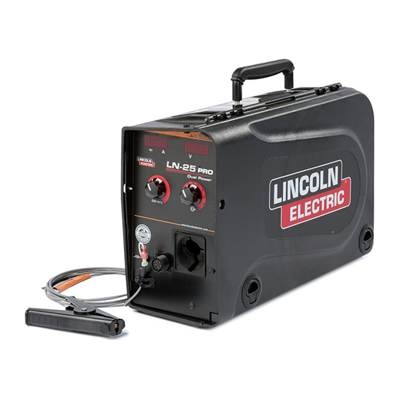
Page 23: Case Front Controls
OPERATION CASE FRONT CONTROLS POWER-UP SEQUENCE Figure B.3 All of the LEDʼs will briefly illuminate during power-up. 1. WIRE FEED SPEED/AMPERAGE DISPLAY Idle The left display shows the preset wire feed speed. The right display shows OCV. The wire feed speed LED is lit. - Page 24 OPERATION 5. SET-UP MENU 2. WIRE FEED SPEED KNOB Use the Wire Feed Speed Knob to adjust the rate of Preparation for WFS Calibration: wire feed speed. • Place the CV/CC switch in CV. Because the wire feeder is powered by the arc volt- age, the full range of wire feed speed may not be •...
- Page 25 OPERATION RUN-IN WFS CALIBRATION “Run-in” refers to the wire feed speed during the time Measurements for adjusting the WFS calibration must from when the trigger is pulled to when an arc is be made before entering the set-up menu. When first struck.
- Page 26 OPERATION LEFT DISPLAY SELECTION The left display can show either amperage or actual WFS during welding. Note that actual WFS is not the same as preset WFS. For example, the preset WFS may be set to 400 ipm, but the arc voltage is only 15V. The actual WFS will be approximately 280 ipm because there is not enough arc voltage to run at 400 ipm.
- Page 27 OPERATION INTERNAL CONTROLS FIGURE B.4 ITEM DESCRIPTION 2-Step Trigger Interlock Switch CV / CC Switch Pressure Adjustment Arm Optional Timer Kit (See Accessories Section) Spool Retainer Spool Brake Gun Bushing, Thumb Screw and Socket Head Cap Screw Drive Hubs Cold Feed Pushbutton LN-25™...
- Page 28 B-10 B-10 OPERATION 2. CV/CC SWITCH INTERNAL CONTROLS DESCRIPTION (See Figure B.4) The CV/CC switch sets the wire feed speed control method for the wire feeder. 1. 2 STEP - TRIGGER INTERLOCK SWITCH In the CV position, the wire feed speed remains constant during The 2 Step - Trigger Interlock welding.
-
Page 29: Rear Controls
B-11 B-11 OPERATION REAR CONTROLS: FIGURE B.5 ITEM DESCRIPTION Gas Purge Pushbutton Flowmeter Shielding Gas Control Cable Electrode Lead (electrode is a 4/0 cable) LN-25™ PRO DUAL POWER... - Page 30 B-12 B-12 OPERATION 1. GAS PURGE PUSHBUTTON (See Figure B.5) The gas solenoid valve will energize but neither the power source output nor the drive motor will be turned on. The Gas Purge switch is useful for setting the proper flow rate of shielding gas. Flow meters should always be adjusted while the shielding gas is flowing.
-
Page 31: Accessories
ACCESSORIES FACTORY INSTALLED EQUIPMENT • K1500-2 Gun Receiver Bushing. DRIVE ROLL KITS USED • See Parts Pages K2330-2 Timer Kit Includes: Panel and harness for adjusting preflow, burnback and postflow times. K2596-2 Plastic Case Includes: a complete engi- neered plastic case. K1796-xx AWG 1/0 Co-Axial Power Cable Includes: 1/0 Coaxial weld... - Page 32 ACCESSORIES Includes: 14 pin to 14 pin wire Control Cable feeder to power source control K1797-xx cable. Includes: Adapter control cable for connecting a Lincoln 42 VAC wire feeder to a 24 Adapter for Competitive Power VAC Miller power source. K2335-1 Sources Requires the digital...
- Page 33 ACCESSORIES K910-1 Ground Clamp Includes: One 300 Amp Ground Clamp. K910-2 Ground Clamp Includes: One 500 Amp Ground Clamp. Gun Receiver Bushing (for guns Includes: Gun receiver bush- K1500-1 with K466-1 Lincoln gun connec- ing, set screw and hex key tors;...
- Page 34 ACCESSORIES Gun Receiver Bushing (for gun Includes: Gun receiver bush- K1500-4 with K466-3 Lincoln gun connec- ing with hose nipple, set screw tors; compatible with Miller® guns.) and hex key wrench. Includes: Gun receiver bushing K1500-5 Gun Receiver Bushing (compatible with hose nipple, 4 guide tubes, with Oxo®...
-
Page 35: Maintenance
MAINTENANCE SAFETY PRECAUTIONS 5. Connect the shielding gas hose to flow meter refer- WARNING ence standard. ELECTRIC SHOCK can kill. 6. Orient the LN-25™ PRO DUAL POWER in a verti- • Turn the input power OFF at the cal position. welding power source before installation or changing drive 7. -
Page 36: Troubleshooting
HOW TO USE TROUBLESHOOTING GUIDE WARNING Service and Repair should only be performed by Lincoln Electric Factory Trained Personnel. Unauthorized repairs performed on this equipment may result in danger to the technician and machine operator and will invalidate your factory warranty. For your safety and to avoid Electrical Shock, please observe all safety notes and precautions detailed throughout this manual. -
Page 37: Digital Display Models Error Codes
TROUBLESHOOTING Observe all Safety Guidelines detailed throughout this manual PROBLEMS POSSIBLE RECOMMENDED (SYMPTOMS) CAUSE COURSE OF ACTION Digital Display Models Error Codes Description Possible Adjustments Fault Code 1. The wire drive motor has over- 1. Check that the electrode slides Err 81 Motor overload, long term. - Page 38 TROUBLESHOOTING Observe all Safety Guidelines detailed throughout this manual PROBLEMS POSSIBLE RECOMMENDED (SYMPTOMS) CAUSE COURSE OF ACTION Output Problems The feeder does power up - no display, no 1. The work sense lead is disconnected or is 1. Connect the work sense lead to the work in cold feed.
- Page 39 TROUBLESHOOTING Observe all Safety Guidelines detailed throughout this manual PROBLEMS POSSIBLE RECOMMENDED (SYMPTOMS) CAUSE COURSE OF ACTION Output Problems Wire feed speed consistently oper- 1. The jumper lead for normal 1. Properly connect the normal ates at the wrong value. The speed speed/extra torque is connected speed/extra torque jumper.
- Page 40 DIAGRAMS ENHANCED DIAGRAM LN-25™ PRO DUAL POWER...
- Page 41 DIMENSION PRINT LN-25™ PRO DUAL POWER...
- Page 42 Do not touch electrically live parts or Keep flammable materials away. Wear eye, ear and body protection. • • • WARNING electrode with skin or wet clothing. Insulate yourself from work and • ground. Spanish No toque las partes o los electrodos Mantenga el material combustible Protéjase los ojos, los oídos y el •...
- Page 43 Keep your head out of fumes. Turn power off before servicing. Do not operate with panel open or • • • WARNING Use ventilation or exhaust to guards off. • remove fumes from breathing zone. Spanish Los humos fuera de la zona de res- •...
- Page 44 • World's Leader in Welding and Cutting Products • • Sales and Service through Subsidiaries and Distributors Worldwide • Cleveland, Ohio 44117-1199 U.S.A. TEL: 216.481.8100 FAX: 216.486.1751 WEB SITE: www.lincolnelectric.com...