Electrolux C240 Service Manual
Extractors
Hide thumbs
Also See for C240:
- Operating manual (24 pages) ,
- Operating and installation manual (20 pages)
Table of Contents
Advertisement
Advertisement
Table of Contents

Related Manuals for Electrolux C240


Summary of Contents for Electrolux C240
-
Page 1: Service Manual
Service Manual C240 - C260 C240R - C260R - C290R 487 03 29 91/EN 08.28... -
Page 3: Table Of Contents
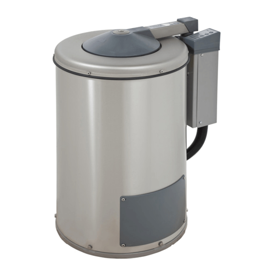
Service manual Machine presentation Overview Technical data Description of principal components Periodic maintenance Service Instruction Function sequences Automatic unit Machine units and components Lid and lid lock Motors Included units somponents Drum 487 03 29 91... - Page 5 Service Machine presentation manual General The extractors described in this manual, with drum volumes 38, 58 and 88 litres, are an invaluable complement to the washing machine and other drying equipment. Through their efficient extraction of the water from the load after a wash program, the drying time can be considerably reduced.
-
Page 6: Machine Presentation
Service Machine presentation manual Safety rules • The machine must not be operated be children. • Do not leave children alone or unsupervised in the vicinity of the extractor. • The machine must not be hosed down with water. • Installation and servicing are to be performed be authorised personnel only. •... -
Page 7: Technical Data
Service 2. Technical data manual Technical data Type C240 (R) C260 (R) C290R Dimensions: Width 515 mm 640 mm 770 mm Depth 660 mm 785 mm 910 mm Height 850/910 mm 870/980 mm 1050 mm Weight 74/85 kg 109/140 kg... -
Page 9: Description Of Principal Components
The machine lid is on a slewing arm, which is swung across the drum opening and then pressed down towards the drum. A microswitch in the control unit and also a Reed element in the C240/C240R and C260/C260R models check that the lid is closed before the machine will start. -
Page 11: Periodic Maintenance
Service 11. Periodic maintenance manual The following maintenance routines should be adhered to, to ensure satisfactory and safe operation, and to prevent service stops. The service intervals set out here are suitable for machines in normal use, for example in a communal laundry in an apartment building. The intervals should be halved if the machines is used intensively, e.g. - Page 13 Service 12. Functions sequences manual Functonal diagram for hydro-ectrator 487 03 29 91 12.1...
- Page 14 Service manual 12. Functions sequences General To facilitate fault-tracing in the electrical system, the description which follows has been divided into function sequences. At the end of this section there is also a table listing a number of measurement points. The following sequences are described here: •...
- Page 15 Service manual 12. Functions sequences Power supply (380 V 60 Hz) Machine power supply can be 380 V 3 AC. An auxiliary tranformer is supplied with two of the line voltage phases and steps down the mains voltage to 24 V control voltage. The auxiliay tranformer is protected by two fuses, one on the primary side (F1) and one on the secondary side (F2).
- Page 16 Service manual 12. Functions sequences Circuit diagram 489 50 01 77 has been used in describing the function sequence in this section: This diagram is in principle identical to all the other circuit diagrams since the control voltage is 24 V AC 50/60 Hz. Start of extraction The machine starts extraction when the operator presses the START button on the control panel.
-
Page 17: Function Sequences
Service manual 12. Functions sequences R1-R2 S3:out 1 S6:out 2 S1:2 S1:4 487 03 29 91 12.5... - Page 18 Service manual 12. Functions sequences Lid Opening The lid is opened by pressing the button on the control panel. The following conditions must be fulfilled before the lid will open: • The machine power supply must be on • The drum must be completely at a standstill i.e. rotation guards H1 (S4:2) and SW2 (S1:7) must have sent the opening signal.
- Page 19 Service 12. Functions sequences manual S1:6 S1:7 S4:2 487 03 29 91 12.7...
- Page 20 Service manual 12. Functions sequences Stop after extraction The machine will stop extracting in the following three cases: • When the preset extractor time has elapsed (approx. 5 minutes). • When the operator presses in the STOP button on the control panel. •...
- Page 21 Service manual 12. Functions sequences S1:4 S1:5 S1:7 S4:2 487 03 29 91 12.9...
- Page 22 Service manual 12. Functions sequences Imbalance during extraction In the event of imbalance, extraction is halted so that the load can be manually redistributed. The sensor arm of the microswitch (SW3) is activated if there is load imbalance, and it in turn sends a signal to the circuit board (S2:2) for activation of the braking function and subsequent possibility of lid opening function.
- Page 23 Service 12. Functions sequences manual S2:2 487 03 29 91 12.11...
- Page 24 Service manual 12. Functions sequences Faults and corrective action required Faults indecated by flashing yellow light Fault Possible cause Action 1. The extractor will not start. Yellow Reed element ring in the deck is Disconnect main power supply to light flashing. defective extractor.
- Page 25 Service manual 12. Functions sequences Fault Possible cause Action 6. Extraction interrupted and lid The motor´s internal thermal protection Disconnect main power supply to remains locked. After the full has cut out the motor during extractor. Remove cover of control unit. extraction time has elapsed and extraction.
- Page 26 Service manual 12. Functions sequences Measurement points A number of measurement points are shown in the adjacent diagram. The table below shows what each measurement is for, where to measure and the value which you should obtain. The measurements described below should be made with extractor in inactive state, i.e. with the drum not rotating.
- Page 27 Service 12. Functions sequences manual 487 03 29 91 12.15...
-
Page 29: Automatic Unit
Service manual 21. Automatic unit Component units (230V 50 Hz; 400- 415V 50 Hz and 440V 60 Hz) Relay, extraction Relay, brake Auxiliary transformer - supplies power to the electronics unit, and provides control voltage 24 V AC to components. The transformer is switchable for mains voltages: 230 V, 400 V, 415 V and 440 V. - Page 30 Service manual 21. Automatic unit Component units (380 V, 60 Hz) Relay, extraction Relay, brake Auxiliary transformer - supplies power to the electronics unit, and provides control voltage 24 V AC to components. The transformer is connected for the mains voltage 380 V.
-
Page 31: Lid And Lid Lock
To prevent the machine from being able to start with the lid open there is a microswitch which detects when the lid lock is engaged. Reed elements in the lid (on the C240/C240R and C260/C260R) sense when the lid is pressed lock down towards the deck. - Page 32 Service manual 29. Lid and lid lock Reed element C240, C240R, C260 and C260R General The function of the Reed element is to check that the lid is properly closed before extraction can start. A complete Reed ring consists of two Reed elements, set the ring itself, beneath the deck.
- Page 33 Service 30. Motors manual Description (230V 50 Hz; 400-415V 50 Hz and 440V 60 Hz) The motor is mounted under the drum and drives the drum directly on its output shaft. To reduce motor noise and vibration the entire drum unit has rubber dampers. On flexibly- mounted models this damping is provided by either eight or ten rubber straps, while the drum models this of R- models is mounted on two relatively rigid rubber bushings.
- Page 34 Service 30. Motors manual Description (380 V, 60 Hz) The motor is mounted under the drum and drives the drum directly on its output shaft. To reduce motor noise and vibration the entire drum unit has rubber dampers. On flexibly- mounted models this damping is provided by either eight or ten rubber straps, while the drum unit of R-models is mounted on two relative rigid rubber bushings.
-
Page 35: Motors
Service 30. Motors manual Fault-tracing Motor does not run at all. • Check the power supply to the motor. Check the motor´s quick connector. • Check the motor windings with an ohmmeter for short-circuit or failure. • Check that the motor shaft can be turned. If it can´t, the probable cause is bearing failure. - Page 37 These are two methods of mounting the drum unit in the frame: one for the flexibly-mounted type, the other for R-model. • In the flexibly-mounted models (C240 and C260) the drum unit is suspended from rubber straps: 8 or 10 according to type.
- Page 38 Service 42. Drum manual R-models (C240R, C260R and C290R) Checking and adjusting the rigidty of the drum mounting. The rigidity of the drum mounting is adjusted by means of the nuts above the bushing: 20-30 mm three nuts or four according to model. Check: •...
- Page 39 Service manual 42. Drum • Remove the bolts around base of outer casing. Lift outer casing and control unit straight upwards. • Remove the three or four nuts securing the bushing. Lift the motor straight upwards. • Replace the two rubber bushings. When you replace the upper bushing, do not remove the supporting journal from the motor.
- Page 40 Share more of our thinking at www.electrolux.com...