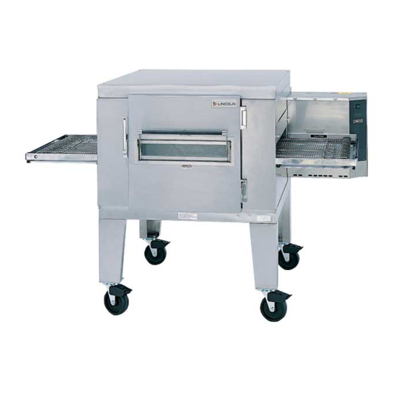
Lincoln 1400 Series Service Manual
1400 series advantage impinger conveyor ovens
Hide thumbs
Also See for 1400 Series:
- Service manual (92 pages) ,
- User manual (13 pages) ,
- Manual (55 pages)
Table of Contents
Advertisement
SERVICE MANUAL
(DOMESTIC AND INTERNATIONAL)
IMPINGER CONVEYOR OVENS
MODEL 1400 SERIES ADVANTAGE
Lincoln Foodservice Products, LLC
1111 North Hadley Road
Fort Wayne, Indiana 46804
United States of America
Phone : (800) 374-3004
U.S. Fax: (888) 790-8193 • Int'l Fax: (260) 436-0735
Technical Service Hot Line
(800) 678-9511
www.lincolnfp.com
1450DomExptSvc
REV: 9/25/08
Advertisement
Table of Contents
Troubleshooting

Related Manuals for Lincoln 1400 Series


Summary of Contents for Lincoln 1400 Series
- Page 1 SERVICE MANUAL (DOMESTIC AND INTERNATIONAL) IMPINGER CONVEYOR OVENS MODEL 1400 SERIES ADVANTAGE Lincoln Foodservice Products, LLC 1111 North Hadley Road Fort Wayne, Indiana 46804 United States of America Phone : (800) 374-3004 U.S. Fax: (888) 790-8193 • Int’l Fax: (260) 436-0735...
-
Page 2: Table Of Contents
OVEN BACK, GAS – ELECTRIC... 40 OVEN BACK, GAS – ELECTRIC BLOW-UP... 41 CONVEYOR – 1450 SERIES ... 42 CONVEYOR 1450 SERIES BLOW-UP ... 43 TABLE OF CONTENTS Impinger I – 1400 Series Advantage Service Manual - Dom & Int’l... -
Page 3: Sequence Of Operation
3A fuse to the normally open single pole main fan switch. Closing the main fan switch supplies 120 VAC to the coil of the main fan relay. The coil of the relay is Impinger I – 1400 Series Advantage Service Manual – Dom & Int’l SEQUENCE OF OPERATION... -
Page 4: Sequence Of Operations
SEQUENCE OF OPERATIONS MODEL 1454 / 380/220 VAC / 50 HZ / 3 PHASE MODEL 1455 / 415/240 VAC / 50 HZ / 3 PHASE Impinger I – 1400 Series Advantage Service Manual - Dom & Int’l... -
Page 5: Sequence Of Operations
Any change in motor load (± RPM) is detected by the sensor and the voltage to the motor is adjusted accordingly. Impinger I – 1400 Series Advantage Service Manual – Dom & Int’l SEQUENCE OF OPERATIONS MODEL 1457 / 220-240 VAC / 50 HZ / L.P. -
Page 6: Schematic 1450 / 1451 / 1480
SCHEMATIC 1450 / 1451 / 1480 Impinger I – 1400 Series Advantage Service Manual - Dom & Int’l... -
Page 7: Schematic 1452 / 1453
SCHEMATIC 1452 / 1453 Impinger I – 1400 Series Advantage Service Manual – Dom & Int’l... -
Page 8: Schematic 1454 / 1455
SCHEMATIC 1454 / 1455 Impinger I – 1400 Series Advantage Service Manual - Dom & Int’l... -
Page 9: Schematic 1456 / 1457
SCHEMATIC 1456 / 1457 Impinger I – 1400 Series Advantage Service Manual – Dom & Int’l... -
Page 10: Schematic 1474 / 1475 / 1476
SCHEMATIC 1474 / 1475 / 1476 Impinger I – 1400 Series Advantage Service Manual - Dom & Int’l... -
Page 11: Troubleshooting Guide
Centrifugal Switch 1475, 1476 See Page 14. Transformer, 24 VAC Burner Blower Motor Impinger I – 1400 Series Advantage Service Manual – Dom & Int’l TROUBLESHOOTING GUIDE GAS OVENS IMPINGER ADVANTAGE SERIES EVALUATION Check breakers, reset if required. Call Power Co. if... - Page 12 Check for blockage of main orifice. If there is no blockage to the main orifice, check the temperature control. Check for 120 VAC across L1 and L2 on temperature control board. Impinger I – 1400 Series Advantage Service Manual - Dom & Int’l...
- Page 13 All lights off - lights of main power, main fan off, oven fan switch out. 1 on 2 off 3 off 4 off 5 off 6 off - Oven Motor Centrifugal Switch open 1 on 2 on 3 on 4 off 5 off 6 off - Burner Motor Centrifugal Switch bad.
- Page 14 Check for supply voltage on both sides of switch. If voltage present on one side only, check for air tube blockage or misalignment, adjust air switch. Replace as needed. Impinger I – 1400 Series Advantage Service Manual - Dom & Int’l...
- Page 15 Spark Generator Igniter/Sensor Assembly Gas valve Impinger I – 1400 Series Advantage Service Manual – Dom & Int’l This switch is located inside the gas valve and should close when gas pressure is present. WITH POWER OFF: remove 3 prong plug (on gas valve) and measure continuity between terminals 2 and 3.NOTE:...
- Page 16 If 220 VAC is present, and unit is not heating, see "Flame Monitor". Check for 220 VAC at terminal "COM" on temperature control board. If no voltage is present, trace wiring back to ignition control. Impinger I – 1400 Series Advantage Service Manual - Dom & Int’l load terminal...
- Page 17 Intermittent heating As Follows Impinger I – 1400 Series Advantage Service Manual – Dom & Int’l Remove thermocouple leads from the temperature control board and measure the millivolt output of these leads. Refer to chart on Page 25 for proper readings.
-
Page 18: Troubleshooting Guide
Terminals are normally closed, but open at 130°F ± 5°F (53.9°C ± 2.8°C). Check for over heating and reset thermostat. Test for proper operation. If it will not reset and hold, then replace. Impinger I – 1400 Series Advantage Service Manual - Dom & Int’l... - Page 19 Speed Adjustment Potentiometer DC Motor Control Board Impinger I – 1400 Series Advantage Service Manual – Dom & Int’l Check for 120 VAC input to temperature control board. If not present, check wiring from Hi-Limit to temperature control board. Turn the temperature adjustment dial to the maximum temperature position.
- Page 20 (mounted on conveyor stepper drive motor. Check all wiring and connections for damage. Check all connections for tightness or proper location and check all wiring for visible damage. Replace as needed. Impinger I – 1400 Series Advantage Service Manual - Dom & Int’l...
-
Page 21: Removal Installation & Adjustments
Shut off power at main breaker. Remove back assembly. (See MOTOR, MAIN FAN)) Reinstall and locate fan so that the bottom of the fan spider is 1 1/2" from the top of the oven back cone. (See Drawing) FAN SPIDER... - Page 22 7. Heater element may now be unbolted and removed. 8. Check heater elements to be sure they are the proper voltage replacement. 9. Reassemble in reverse order. NOTE: Be sure the heating element connections are tight. Impinger I – 1400 Series Advantage Service Manual - Dom & Int’l...
- Page 23 10. Reassemble in reverse order - after assembly is complete, be sure to check manifold pressure (3.5" W.C. NAT GAS 10" W.C. LP) and adjust if necessary. (See Section "MANIFOLD PRESSURE - ADJUSTMENT") NOTE: Check all gas line fittings for leaks after installation. Impinger I – 1400 Series Advantage Service Manual – Dom & Int’l...
- Page 24 Place a temperature sensor in the center of the oven between top two middle fingers and set temperature control to 500°F, allow temperature to stabilize (approx. 30 min.) and adjust knob to actual temperature.
- Page 25 5.46 6.99 64°F 4.01 5.52 7.05 62°F 4.06 5.57 7.10 60°F 4.12 5.63 7.16 Impinger I – 1400 Series Advantage Service Manual – Dom & Int’l 7.06 7.83 9.37 10.14 7.12 7.89 9.43 10.20 7.17 7.94 9.49 10.26 7.23 8.00 9.54...
-
Page 26: Conveyor Control Board Assembly - Replacement
2. Remove control panel top. 3. Remove cover from relay box. 4. Reverse wires fastened to terminals A+ and A- on conveyor control board 5. Reassemble in reverse order. Impinger I – 1400 Series Advantage Service Manual - Dom & Int’l... - Page 27 5. Remove wires from back of switch, note wire number and location. 6. Reassemble in reverse order and check system operation. NOTE: Make sure switch housing is fully seated in control box housing. Impinger I – 1400 Series Advantage Service Manual – Dom & Int’l...
- Page 28 Reassemble in reverse order and check 10. for leaks around the cover. SIDE VIEW FILTER COVER PLATE TOP VIEW PRESSURE CONTROLLER ADJUSTMENT FILTER COVER PLATE Impinger I – 1400 Series Advantage Service Manual - Dom & Int’l OUTPUT MANIFOLD PRESSURE ADJUSTMENT ELECTRICAL CONNECTOR ELECTRICAL CONNECTOR...
- Page 29 NOTE: Voltage output of the secondary is to be 120 VAC ± 10%. Check for this output at the secondary before installing leads to the secondary. If voltage above or below is measured, recheck the position of the primary leads. Impinger I – 1400 Series Advantage Service Manual – Dom & Int’l...
-
Page 30: General - 1450 Series
Adjustable Leg Caster 6” Insulation Holder Assy. Finger Housing Columnating Panels – See Installation Manual Finger Cover Crumb Pan, Internal Window Frame, Bottom Glass, Access Window Window Frame, Top Impinger I – 1400 Series Advantage Service Manual - Dom & Int’l... -
Page 31: General - 1450 Series Blow-Up
GENERAL - 1450 SERIES BLOW-UP Impinger I – 1400 Series Advantage Service Manual – Dom & Int’l... -
Page 32: Control Box - 1450, 1451, 1480
Conveyor Motor and Gear Box Assy. 10 Tooth Sprocket Bracket, Hall Effect Hall Effect Sensor Cooling Fan, Control Box Hall Effect Cable Face Plate, Temperature Front Cover Air Shutter Plate, Air Shutter Impinger I – 1400 Series Advantage Service Manual - Dom & Int’l... -
Page 33: Control Box - 1450, 1451, 1480 Blow-Up
CONTROL BOX – 1450, 1451, 1480 BLOW-UP Impinger I – 1400 Series Advantage Service Manual – Dom & Int’l... -
Page 34: Control Box - 1452, 1453
Hall Effect Sensor Bracket, Hall Effect Finger Guard, Cooling Fan Conveyor Control Pot. Cooling Fan, Control Box Hall Effect Cable Thermocouple Front Cover Pilot Light Face Plate, Temperature Impinger I – 1400 Series Advantage Service Manual - Dom & Int’l... -
Page 35: Control Box - 1452, 1453 Blow-Up
CONTROL BOX – 1452, 1453 BLOW-UP Impinger I – 1400 Series Advantage Service Manual – Dom & Int’l... -
Page 36: Contol Box - 1454, 1455
Finger Guard, Cooling Fan Conveyor Control Pot. Cooling Fan, Control Box Junction Box Terminal Block, 5 Pole Junction Box Cover Thermocouple Pilot Light Front Cover Assy Face Plate, Temperature Impinger I – 1400 Series Advantage Service Manual - Dom & Int’l... -
Page 37: Control Box - 1454, 1455 Blow-Up
CONTROL BOX – 1454, 1455 BLOW-UP Impinger I – 1400 Series Advantage Service Manual – Dom & Int’l... -
Page 38: Control Box - 1456, 1457, 1474, 1475, 1476
Magnet, 8 Pole Flame Target Bracket, Hall Effect Hall Effect Sensor Switch, Burner Reset Thermostat, Hi-Limit Flange Burner 07 AMP Circuit Breaker Motor Relay Control, Conveyor Ignition control Blower Motor Impinger I – 1400 Series Advantage Service Manual - Dom & Int’l... -
Page 39: Control Box - 1456, 1457, 1474, 1475, 1476 Blow-Up
CONTROL BOX – 1456, 1457, 1474, 1475, 1476 BLOW-UP Impinger I – 1400 Series Advantage Service Manual – Dom & Int’l... -
Page 40: Oven Back, Gas - Electric
Oven Back Assy – Gas Stand Off Inlet Panel Fan, Main Wire Form Thermostat Bulb Oven Back Assy. – Electric Heating Element, 208V Heating Element, 220V Heating Element, 240V Impinger I – 1400 Series Advantage Service Manual - Dom & Int’l... -
Page 41: Oven Back, Gas - Electric Blow-Up
OVEN BACK, GAS – ELECTRIC BLOW-UP Impinger I – 1400 Series Advantage Service Manual – Dom & Int’l... -
Page 42: Conveyor - 1450 Series
Retaining Ring Conveyor Bearing Block Roll, Conveyor, Notched Conveyor Idler Shaft Conveyor Pan Stop Connecting Link Conveyor Drive Shaft Roller Chain Sprocket Crumb Pan Conveyor Frame Drive Chain Impinger I – 1400 Series Advantage Service Manual - Dom & Int’l... -
Page 43: Conveyor 1450 Series Blow-Up
CONVEYOR 1450 SERIES BLOW-UP Impinger I – 1400 Series Advantage Service Manual – Dom & Int’l... - Page 44 1111 North Hadley Road Fort Wayne, Indiana 46804 United States of America Telephone: (260) 459-8200 U.S. Facsimile: (888) 790-8193 Int’l Facsimile: (260) 436-0735 Technical Service Hotline: (800) 678-9511 www.lincolnfp.com Impinger I – 1400 Series Advantage Service Manual - Dom & Int’l...